Mazda Astina (1995 – 1998) – fuse and relay box diagram
Year of production: 1995, 1996, 1997, 1998
The Mazda 323F (also known as the 323 Astina or Lantis) was produced between 1994 and 1998. This article provides fuse box diagrams for the 1995, 1996, 1997, and 1998 models, along with details on the fuse panel locations inside the vehicle and the function and layout of each fuse and relay.
Passenger compartment fuse box
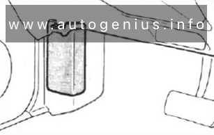
Fuse Box Location
The interior fuse panel is located behind a cover below the instrument panel on the driver’s side.
Fuse Box Diagram
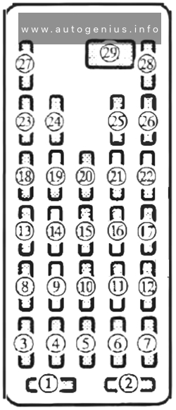
Assignment of the fuses in the passenger compartment
| № | Name | Amps | Description |
|---|---|---|---|
| 1 | – | – | – |
| 2 | ROOM | 15A | Interior lights, Luggage compartment light |
| 3 | S/ROOF | 15A | Sunroof |
| 4 | METER | 15A | Gauge, Backup light |
| 5 | P.WIND | 30A | Power windows |
| 6 | HORN | 10A | Horn |
| 7 | – | – | – |
| 8 | R.WIP | 10A | Rear wiper |
| 9 | DEFOG | 20A | Rear defroster |
| 10 | A/C | 10A | Air conditioner |
| 11 | – | – | – |
| 12 | – | – | – |
| 13 | ENGINE | 10A | Engine switch |
| 14 | WIPER | 20A | Front wipers |
| 15 | P.WIND | 30A | Power windows |
| 16 | TAIL | 10A | Tail lights |
| 17 | – | – | – |
| 18 | RADIO | 15A | Audio |
| 19 | TURN | 10A | Turn signal |
| 20 | – | – | – |
| 21 | STOP | I5A | Biake light, Taillight |
| 22 | – | – | – |
| 23 | CIGAR | 15A | Cigarette lighter |
| 24 | – | – | – |
| 25 | D.LOCK | 30A | Power door lock |
| 26 | – | – | – |
| 27 | SPARE | 10A | – |
| 28 | SPARE | 15A | – |
| 29 | HEATER | 40A | Climate control system |
Engine compartment fuse box
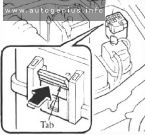
Fuse Box Location
Open the fuse block cover by unhooking the tabs and lifting up on the cover.
Fuse Box Diagram
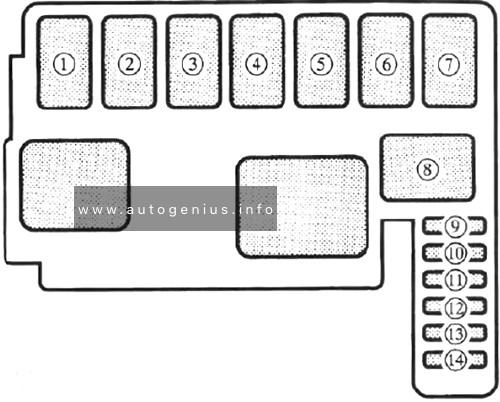
Assignment of the fuses in the engine compartment
| № | Name | Amps | Description |
|---|---|---|---|
| 1 | HEAD | 30A | ROOM, TOWER WINDOW and DOOR LOCK fuses |
| 2 | INJ | 30A | Fuel injection system |
| 3 | MAIN | 80A 100A (2.0L) |
For protection of all circuits |
| 4 | AD FAN | 30A | Additional fan (Air conditioner) |
| 5 | IG KEY | 50A | RADIO, TERN, METER, ENGINE fuses, Ignition system |
| 6 | ABS | 40A | Anti-lock brake system |
| 7 | BTN | 60A | Headlight |
| 8 | COOLING FAN | 20A/30A | Cooling fan |
| 9 | HAZARD | 15A | Hazard warning flasher |
| 10 | A/C | 10A | Air conditioner |
| 11 | – | – | – |
| 12 | FOG | 20A | Fog light |
| 13 | ST SIGN | 10A | Starter |
| 14 | – | – | – |
Replacing the MAIN fuse
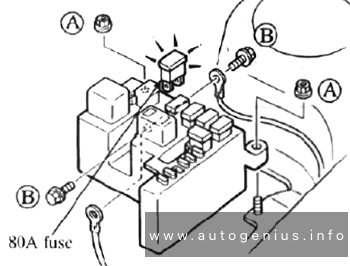
- Make sure the ignition is off.
- Remove the negative battery terminal.
- Remove nuts A.
- Lift the fuse block and remove bolts B.
- Replace the fuse with a new one of the same rating.
- Install in the reverse order of removal.
WARNING: Terminal and harness assignments for individual connectors will vary depending on vehicle equipment level, model, and market.