Volkswagen Polo (6N/6KV; 1997 – 1998) – fuse and relay box diagram
Year od production: 1997, 1998
This article covers the third-generation Volkswagen Polo (Typ 6N/6KV), manufactured between 1994 and 1996. It includes fuse box diagrams for the 1995 through 2002 models, details the locations of the fuse panels within the vehicle, and provides information on the fuse and relay assignments (fuse layout)
Passenger Compartment
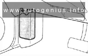
Fuse box location
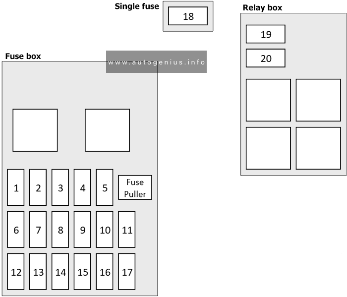
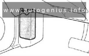
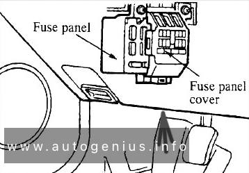
The fuse box is located behind the cover in driver’s storage compartment.
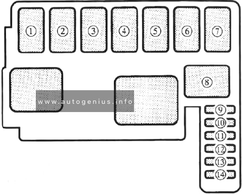
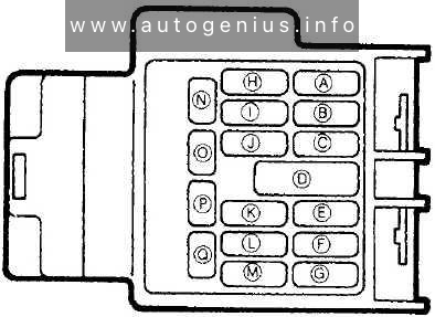
Fuse box diagram
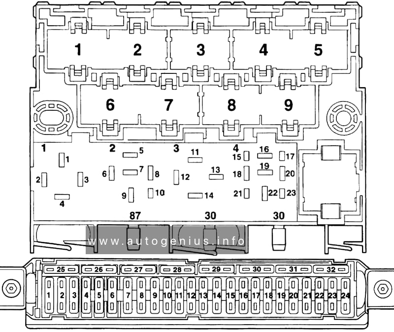
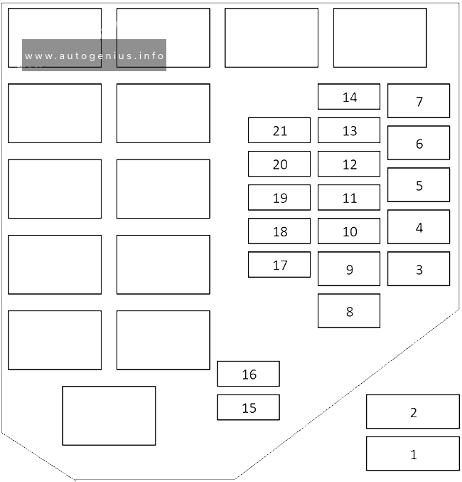
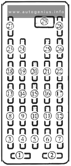
Volkswagen Polo (6N/6KV; 1997 – 1998) – fuses and relay box diagram – passenger compartment
Assignment of the fuses in the instrument panel
№
Amps
Description
1
15A
Engine control unit
2
10A
Engine control unit (only on petrol engines)
Engine electrics (only on diesel engines)
3
7.5A
Engine electrics
4
15A
Ignition transformer
5
10A
Auto, gearbox control unit, shift lock
6
5A
Auto, gearbox control unit
7
5A
ABS control unit
8
15A
Injectors, Lambda probe
9
10A
Engine control unit
10
15A
Engine control unit (only on petrol engines)
Engine electrics (only on diesel engines)
11
15A
Horn, seat heating
12
10A
Right main beam, main beam warning lamp
13
10A
Left main beam
14
10A
Right dipped beam, right headlight range control, headlight range control adjuster
15
10A
Left dipped beam, left headlight range control
16
5A
Right side and tail lights
17
5A
Left side and tail lights
18
7.5A
Reversing light, heated washer jets, selector lever illumination
19
15A
Fog lights, rear fog light
20
10A
Brake lights
21
10A
Hazard warning lights
22
5A
Turn signals
23
15A
Windscreen wipe/wash system
24
10A
Rear window wiper, heated and adjustable exterior mirrors
Year of production: 1996, 1997, 1998, 1999, 2000, 2001, 2002, 2003, 2004, 2005, 2006
This article focuses on the second-generation Volkswagen Transporter LT (Typ 2D), which was produced between 1996 and 2006. It includes fuse box diagrams for Volkswagen LT models from 1996 through 2006, along with information on the location of the vehicle’s fuse panels. You will also find details on the fuse and relay assignments (fuse layout) for each model year.
Passenger Compartment Fuse Box
Fuse Box Location
The fuse box is located behind an access panel in the steering column.
The placement of auxiliary relay carriers and fuse carriers is not standardized; it varies depending on the specific equipment installed in the vehicle.
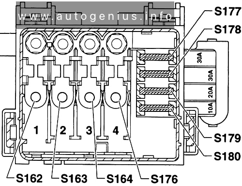
Relay carrier under driver seat
Assignment of the relays in the relay carrier
№
Amps
Description
S171
15A
Battery isolation relay fuse
S41
30A
Heated rear window single fuse
S160
15A
Heated passenger’s seat fuse
S159
15A
Heated driver’s seat fuse
S161
10A
Trailer operation turn signal relay fuse
S188
10A
Roof mounted turn signals fuse
S187
15A
Differential lock fuse
S147
15A
Relief relay fuse
S37
25A
Power window fuse (driver’s side)
S170
25A
Fuse for electric windows (front passenger side)
S97
30A
Fresh air blower fuse
S23
25A
Heater fuse (Additional air heater B1LC/D1LC / B3LC/D3LC)
S53
60A
ABS hydraulic pump fuse/valves
S186
15A
Tilt device fuse
S136
15A
Air conditioning system fuse
S81
20A
Fuel pump fuse (Engine codes: AGL)
S42
20A
Radiator fan fuse
S254
15A
Optional equipment fuse (Additional exterior and interior installations)
S219
15A
Power take-off fuse
S219
15A
Power take-off/speed regulation fuse (Engine codes: AHD)
S82
10A
Continued circulation of coolant pump fuse (Engine codes: AHD, AGX, AGK)
S53
50A
ABS return flow pump fuse (ABS control unit)
S106
25A
Rotating light fuse
S150
20A
Headlight washer system fuse
S190
15A
Terminal 30 voltage supply fuse (Heated rear window delay relay, magnetic coupling control unit, battery split charge relay)
S148
10A
Mirror adjustment /heater fuse
S64
20A
Socket fuse
S124
7.5A
ABS control unit fuse
S124
10A
ABS control unit fuse
S220
7.5A
Daylight driving lights fuse (from May 1997)
S172
15A
Daylight driving light fuse (left dipped beam)
S174
15A
Daylight driving light fuse (left side and tail lights) (up to April 1997)
S175
15A
Daylight driving light fuse (right side and tail lights) (up to April 1997)
S49
15A
Siren fuse
S54
25A
ABS valves fuse
S51
10A
Warm air blower 1st and 2nd speeds fuse
S118
25A
Warm air blower and coolant shut-off valve fuse
S52
25A
Central locking fuse
S290
30A
Fuel filter heating fuse
S175
15A
Daylight driving light fuse (side and tail lights) (from May 1997)
S173
15A
Daylight driving light fuse (right dipped beam)
Auxiliary relay carrier on the flap under the driver’s seat
Assignment of the relays in the relay carrier
№
Designation/function
Terminal 15 relief relay
Terminal D+ relief relay
Fuel pump relay (Engine codes: AGL)
Fresh air blower relay
Air conditioning system switch-off relay
Magnetic coupling relay
Headlight washer system relay
Horn relay
Terminal 30 voltage supply relay (Engine codes: AHD, AGX)
Daylight driving light relay (dipped beam)
Daylight driving light relay (left dipped beam) (from May 1997)
Daylight driving light relay (right dipped beam) (from May 1997)
Daylight driving relay (side and tail lights)
Magnetic coupling control unit (Engine codes: AGL)
Auxiliary relay carrier and control units under driver’s seat at rear
Assignment of the relays in the relay carrier
№
Designation/function
Battery split charge relay
Trailer operation turn signal relay
Roof mounted turn signals relay
Daylight driving lights switch-on relay
Rotating light relay
Airbag/seat belt tensioner control unit
CCS control unit (Engine codes: AGL)
Coolant shortage indicator control unit (Discontinued from August 1998)
Rotating light and siren system control unit
Central locking control unit
Diesel direct injection system control unit
Motronic control unit (Engine codes: AGL 105 KW)
Fuel filter heater relay
Tilt device relay
Magnetic coupling cut-out relay, air conditioning system
Radiator fan relay
Delay relay
Relay carrier on right in engine compartment
Assignment of the relays in the relay carrier
№
Description
–
Radiator fan 4th speed relay
–
Automatic intermittent wash/wipe and Hazard warning light relay control unit
Relay carrier on left in engine compartment
Assignment of the relays in the relay carrier
№
Amps
Designation/function
S39
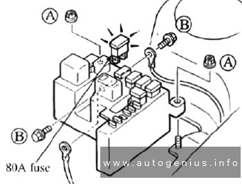
80A
Strip fuse for glow plugs (Engine codes: AHD, AGX, AGK)
Glow plug relay (Engine codes: AHD, AGX)
Glow plug relay (Engine codes: AGK)
ABS with EDL control unit
Immobilizer control unit
WARNING: Terminal and harness assignments for individual connectors will vary depending on vehicle equipment level, model, and market.
Acura EL (1.6 EL) (1997 – 2000) – fuse and relay box diagram
Years of production: 1997, 1998, 1999, 2000
This article focuses on the first-generation Acura EL (1.6EL), manufactured between 1997 and 2000. It includes fuse box diagrams for the 1997, 1998, 1999, and 2000 models, provides details on the location of the fuse panels within the vehicle, and explains the function of each fuse (fuse layout).
Passenger Compartment Fuse Box
Fuse Box Location
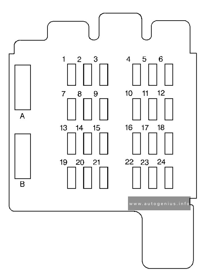
The interior fuse box is located below the dashboard.
Fuse Box Diagram
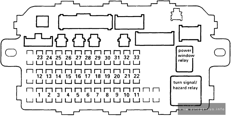
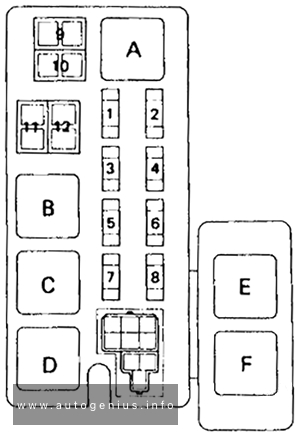
Acura EL (1997 – 2000) – fuses and relay box diagram – passenger compartment
Assignment of the fuses in the instrument panel
№
Amps
Circuit(s) Protected
1
–
Not used
2
–
Not used
3
–
Not used
4
10A
Resistor
Right headlight (high beam)
5
10A
High beam indicator
Left headlight (high beam)
Resistor
A/C compressor clutch relay
A/C thermostat
Condenser fan relay
Heater control panel
Mode control motor
Power mirror actuator
Power mirror defogger
Radiator fan relay
Recirculation control motor
Option connector
18
7.5A
Daytime runninq liqhts control unit
19
7.5A
Back-up lights
20
10A
Daytime running lights control unit
Keyless/security control unit
21
10A
Right headlight (low beam)
22
10A
Left headlight (low beam)
23
10A
SRS unit (VB)
24
7.5A
Moonroof open relay
Moonroof close relay
Power window relay
25
7.5A
ABS indicator circuit
A/T gear position dimming circuit
Clock
Cruise indicator circuit
Gauge assembly
Interlock control unit
Shift lock solenoid
SRS indicator circuit
Integrated control unit
26
20A
Windshield wiper motor
Windshield washer motor
27
15A
Accessory power socket
28
15A
Audio unit
Stereo amplifier (AFB sound system)
Option connector
29
–
Not used
30
7.5A
Audio unit light
A/T gear position console light
A/T gear position indicator dimming circuit
Clock
Cruise indicator circuit
Cruise main switch light
Dash lights brightness controller
Gauge lights
Hazard warning switch light
Heater control panel lights
Integrated control unit
Option connector
31
7.5A
ECM (M/T)
PCM (A/T)
PGM-FI main relay
Keyless/security control unit
Starter cut relay
Integrated control unit
32
7.5A
Front parking lights
License plate lights
Taillights
33
7.5A
Key interlock solenoid
Engine Compartment Fuse Box
Fuse Box Location
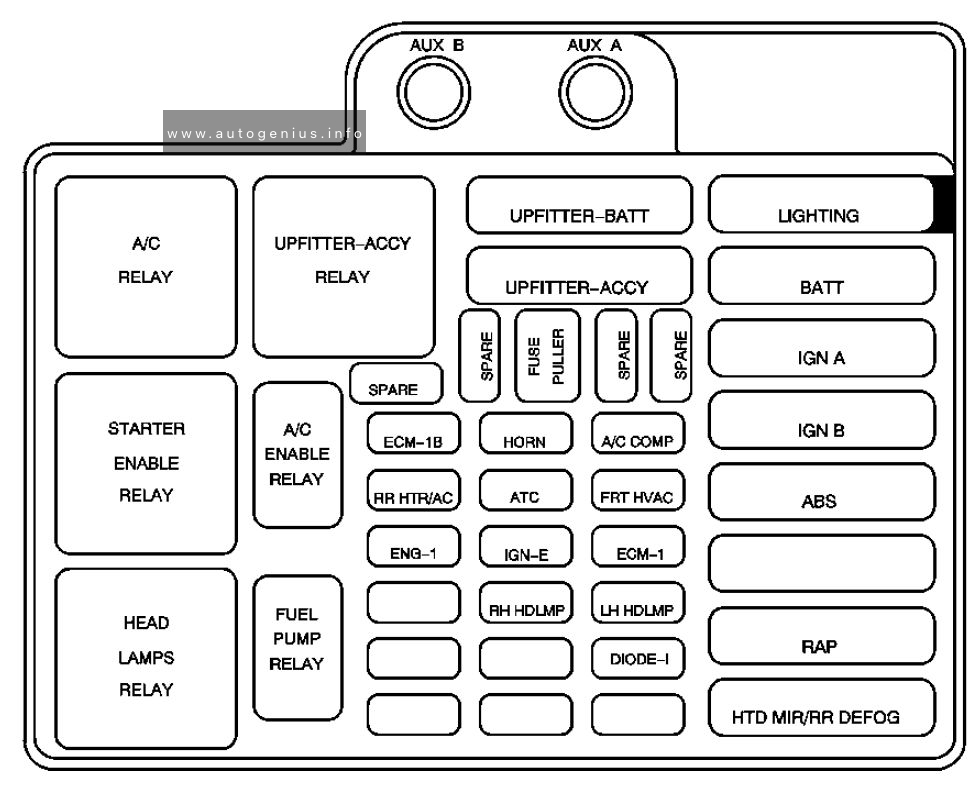
The under-hood fuse box is on the passenger’s side, next to the battery.
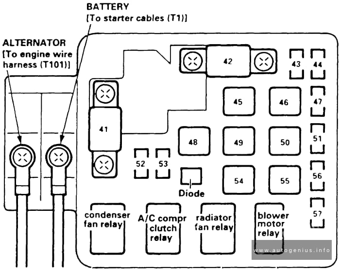
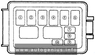
Fuse Box Diagram
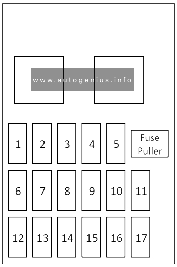
Acura EL (1997 – 2000) – fuses and relay box diagram – engine compartment
Assignment of the fuses in the engine compartment
№
Amps
Circuit(s) Protected
41
80A
All
42
40A
Ignition switch (BAT)
43
7.5A
Ceiling light
Data link connector
Trunk light
Integrated control unit (under-dash fuse relay/box socket)
44
15A
PGM-FI main relay
45
–
Not used
46
40A
Power window relay
47
7.5A
Audio unit
Clock
ECM (M/T)
Heater control panel
PCM (A/T)
Security indicator
Years of production: 1990, 1991, 1992, 1993, 1994, 1995, 1996, 1997
The Volkswagen Taro, a pickup truck, was produced from 1989 to 1997. This article includes fuse box diagrams for the 1990 through 1997 models, provides details on the locations of the fuse panels inside the vehicle, and explains the function of each fuse and relay (fuse layout).
The Mitsubishi FTO (DE), a 2-door coupe, was manufactured from 1994 to 2000. This article provides fuse box diagrams for the 1997, 1998, 1999, and 2000 models, details the locations of the fuse panels inside the vehicle, and outlines the function of each fuse (fuse layout)
Keyless entry receiver, motor antenna assembly, spare connector for radio
16
10A
A/C-ECU power supply, TCL-ECU power supply, MUT-II power supply, engine-ECU power supply, key cylinder illumination lamp, keyless entry receiver, speedometer, trunk room lamp, clock, door-ajar indicator lamp, buzzer-ECU power supply, map lamp, motor antenna assembly, spare connector for radio
17
10A
A/C compressor
18
10A
High beam indicator lamp
19
10A
Illumination lamp, tail lamp, position lamp, license plate lamp, buzzer-ECU
This article focuses on the second-generation Mitsubishi Eclipse, manufactured between 1995 and 1999. It includes fuse box diagrams for the 1995, 1996, 1997, 1998, and 1999 models, details the locations of the fuse panels within the vehicle, and explains the function of each fuse (fuse layout).
Circuits using dedicated fuses №17 and 20 (engine compartment), circuit using multi-purpose fuses №1, 5, 6, 10, and 11 (instrument panel)
2
100A/120A
Charging system, fusible links №1 and 4 (engine compartment).
3
30A
Convertible top
4
30A/40A
Power seat and power windows
5
20A
MPI/MFI system, ELC 4-speed AT and immobilizer system
6
40A
Charging system, fog lights, circuits using headlamp relay, and circuit using tail lamp relay
7
30A
Fuse №17 (instrument panel) and ignition switch
8
30A
Air conditioner and cooling system / Radiator fan
9
50A
Anti-skid braking system (ABS)
10
–
–
11
15A
Anti-lock braking system, auto-cruise control system and stop lamp
12
15A
Horn
13
15A
Turn-signal lamp and hazard lamp
14
10A/15A
Tail lamp, position lamp and licence plate lamp (10A);
Glove compartment light, license plate fight, lighting monitor buzzer, rheostat, side marker light, taillight and illumination light (15A)
15
15A
Front fog lamp
16
10A
Headlamp and headlamp leveling system / Hight-beam indicator light
17
10A
Air conditioner
18
20A
Air conditioner and cooling system
19
10A
Air conditioner, auto-cruise control system, cigarette lighter, front fog lamp, glove box lamp, heater, headlamp leveling system, headlamp washer, lighting monitor buzzer, meter and gauge, radio with tape player, rear fog lamp, rear window defogger, rear wiper and washer, remote controlled mirror, tail lamp, position lamp, licence plate lamp, turn-signal lamp and hazard lamp
20
10A
Anti-lock braking system, auto-cruise control system, central door locking system, door lamp, foot lamp, luggage compartment lamp, ignition key cylinder illumination lamp, immobilizer system, lighting monitor buzzer, meter and gauge, MPI system, radio with tape player, rear window, defogger and supplemental restraint system
WARNING: Terminal and harness assignments for individual connectors will vary depending on vehicle equipment level, model, and market.
This article focuses on the second-generation GMC Safari, produced from 1996 to 2005. It includes fuse box diagrams for the 1996 to 1998 models, along with information on the locations of the fuse panels inside the vehicle and details about the function and layout of each fuse and relay.
Passenger Compartment Fuse Box
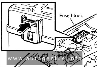
Fuse box location
The fuse block is on the lower portion of the instrument panel on the driver’s side.
The Mazda 323F (also known as the 323 Astina or Lantis) was produced between 1994 and 1998. This article provides fuse box diagrams for the 1995, 1996, 1997, and 1998 models, along with details on the fuse panel locations inside the vehicle and the function and layout of each fuse and relay.
Passenger compartment fuse box
Fuse Box Location
The interior fuse panel is located behind a cover below the instrument panel on the driver’s side.
Year of production: 1989, 1990, 1991, 1992, 1993, 1994, 1995, 1996, 1997
This article covers the first-generation Mazda MX-5 Miata (NA), produced between 1989 and 1997. It includes fuse box diagrams for the 1989–1997 models, provides details on the locations of the fuse panels inside the vehicle, and explains the function and layout of each fuse and relay.