Year of production: 1978, 1979, 1980, 1981, 1982, 1983
This article covers the second-generation AMC Concorde, produced from 1978 to 1983. It includes fuse box diagrams for the 1978, 1979, 1980, 1981, 1982 and 1983 models, provides details on the location of the fuse panels inside the vehicle, and explains the function and layout of each fuse.
Fuse box diagram
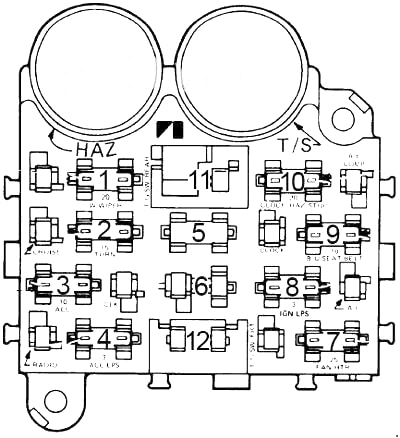
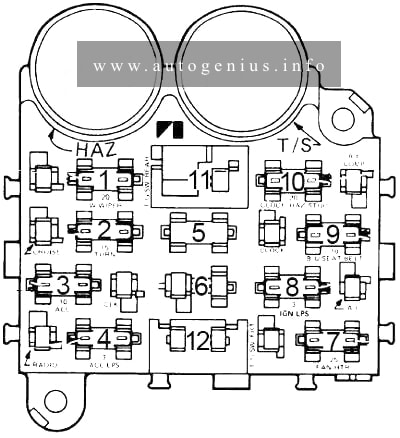
AMC Concord – fuse box diagram
Assignment of the fuses in the fuse box
No.
A
Protected Component
1
10
Parking lights, key/headlights warning buzzer
2
15
Stop light and hazard warning
3
–
–
4
3
Cluster illumination
5
–
–
6
–
–
7
25
Heater/blower motor, A/C clutch
8
15
Radio, cigar lighter
9
15
Turn signals, backup lights, windshield washers
10
5
Gauges, seat belt warning
11
30
Power door lock, power windows circuit breaker
12
25
Heated rear window
Circuit Breaker:
Headlights — 20 amp. circuit breaker in headlight switch
Windshield Wiper — 6 amp. circuit breaker in wiper switch.
Power Windows & Tailgate Switches — 20 amp. circuit breakers located in instrument panel.
WARNING: Terminal and harness assignments for individual connectors will vary depending on vehicle equipment level, model, and market.
This article covers the second-generation AMC Spirit, produced from 1979 to 1983. It includes fuse box diagrams for the 1979, 1980, 1981, 1982 and 1983 models, provides details on the location of the fuse panels inside the vehicle, and explains the function and layout of each fuse.
Year of production: 1977, 1978, 1979, 1980, 1981, 1982, 1983, 1984
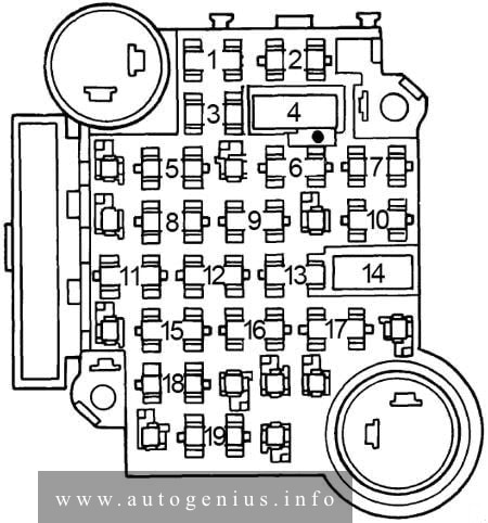
This article covers the Buick Century. It includes fuse box diagrams for the 5th generation 1977, 1978, 1979, 1980, 1981, 1982, 1983 and 1984 models, provides details on the location of the fuse panels inside the vehicle, and explains the function and layout of each fuse.
Instrument illumination, headlight warning and electronic air conditioning
2
20
Electric choke
3
5
Instrument illumination, headlight warning
4
30
Circuit breaker: Power windows and roof, fuel cap lock release
5
—
—
6
25
Heater, air conditioning, trunk lid release, radio capacitor
7
10
Electronic Control Module
8
10
Diesel engine fuse
9
25
Windshield wiper and washer
10
20
Hazard and stop lights
11
20
Seat belt light and buzzer, trunk ajar, transmission downshift and C-4 or E.S.C. jumper, heated back light relay, map and fuel economy lights, instrument gauges and indicator lights
12
20
Tail, side marker, parking and license lights, clock radio
13
10
Radio, cruise control
14
30
Circuit breaker: Power seats, door locks, heated rear window feed, tailgate window
15
20
Turn signal and back-up lights
16
20
Cigar lighter, glove box light, speed and key warning buzzer, power antenna, clock radio, clock, pulse wiper, air conditioning
17
20
Dome and sail panel lights, trunk light, reading light, vanity light, headlight on warning, automatic door locks and rear cigar lighter, tailgate ajar
18
—
—
19
10
Instrument gauges, indicator lights, transmission converter clutch and cruise control, Electric choke
Circuit Breaker: Headlight Circuit — A thermo circuit breaker is incorporated in the headlight switch assembly to protect headlight circuits. Windshield Wiper — Integral with windshield wiper motor.
WARNING: Terminal and harness assignments for individual connectors will vary depending on vehicle equipment level, model, and market.
Year of production: 1972, 1973, 1974, 1975, 1976, 1977, 1978, 1979, 1980, 1981, 1982, 1983
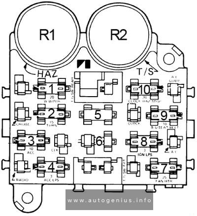
Fuse box diagram
Jeep Wagoneer – fuse and relay box diagram
Assignment of the fuses in the fuse box
№
A
Protected Component
1
20
Windshield wipers
2
15
Turn signals
3
10
Accessories
4
3
Instrument and accessory lights
5
20
Interior lights
6
20
Brake, tail and parking lights
7
25
Air conditioner, heater and electric fan
8
3
Instruments
9
25
Seat belt warning and back-up lights
10
20
Hazard flasher, clock and stop lights
Relay
R1
Hazard flasher
R2
Turn signal
24 amp. circuit breaker is located in the headlight switch to protect headlight circuit. All models have two 30 amp. circuit breakers located in the fuse block to protect the electric tailgate window. One circuit breaker protects the instrument panel switch and the other protects the tailgate switch.
The 6-cyl. models have a 4 amp. in-line fuse protecting the cruise control. The V8 models have a 1.5 amp. in-line fuse protecting the cruise control.
All Jeep models are equipped with fusible links, located in the engine compartment, which protect the circuits.
WARNING: Terminal and harness assignments for individual connectors will vary depending on vehicle equipment level, model, and market.
Audi 200 (C3; 1983 – 1991) – fuse and relay box diagram
Year of production: 1983, 1984, 1985, 1986, 1987, 1988, 1989, 1990, 1991
This article covers the second-generation Audi 200 (C3), produced from 1983 to 1991. It includes fuse box diagrams for the 1983, 1984, 1985, 1986, 1987, 1988, 1989, 1990 and 1991 models, provides details on the location of the fuse panels inside the vehicle, and explains the function and layout of each fuse.
Fuses box diagram
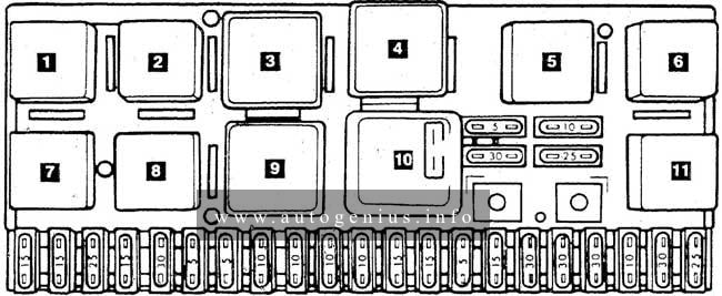
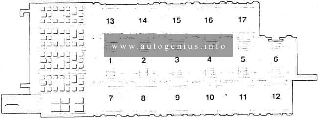
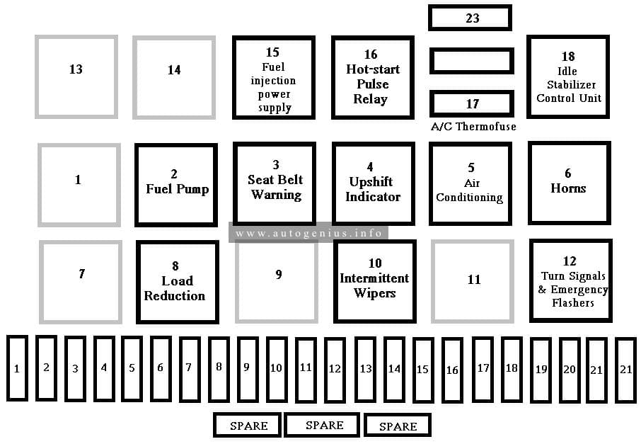
Audi 200 (C3; 1983 – 1991) – fuse and relay box diagram
Audi 100 (C3; 1983 – 1991) – fuse and relay box diagram
Year of production: 1983, 1984, 1985, 1986, 1987, 1988, 1989, 1990, 1991
This article covers the second-generation Audi 100 (c3), produced from 1983 to 1991. It includes fuse box diagrams for the 1983, 1984, 1985, 1986, 1987, 1988, 1989, 1990 and 1991 models, provides details on the location of the fuse panels inside the vehicle, and explains the function and layout of each fuse.
Fuses box diagram
Audi 100 (C3; 1983 – 1991) – fuse and relay box diagram
Volkswagen Rabbit GTI (A1, Type 17; 1974 – 1984) – fuse and relay box diagram
Year of production: 1974, 1975, 1976, 1977, 1978, 1979, 1980, 1981, 1982, 1983, 1984
This article covers the Volkswagen Rabbit, manufactured from 1974 to 1984. It includes fuse box diagrams for the 1974 to 1984 models, provides details on the location of the fuse panels inside the vehicle, and explains the function and layout of each fuse and relay.