Volkswagen Polo (MK6; 2018 – 2020) – fuse and relay box diagram
Year od production: 2018, 2019, 2020
This article covers the sixth-generation Volkswagen Polo (AW1/EW1), produced from 2018 to the present. It includes fuse box diagrams for the 2018, 2019 and 2020 models. You will find information on the location of the fuse panels within the vehicle, as well as detailed descriptions of the fuse and relay assignments (fuse layout).
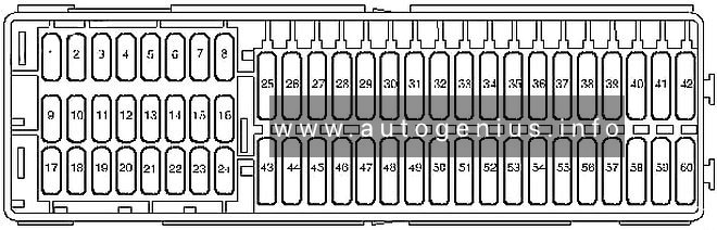
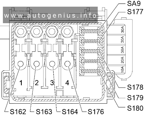
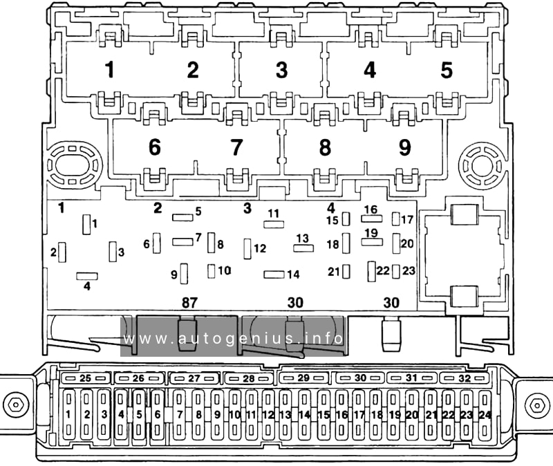
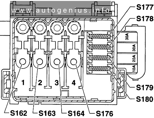
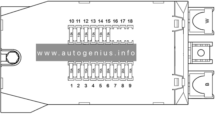
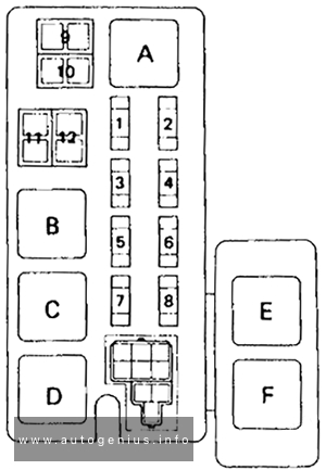
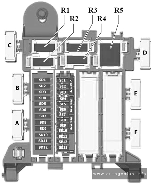
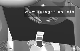
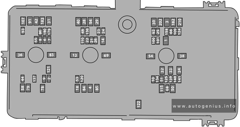
Passenger Compartment Fuse Box
Fuse Box Diagram
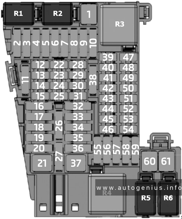
Assignment of the fuses in the passenger compartment
| № | Amps | Function / component |
|---|---|---|
| F1 | 20 A | Trailer detector control unit |
| F2 | – | – |
| F3 | 30 A | Amplifier |
| F4 | – | – |
| F5 | 30 A | Sliding sunroof adjustment control unit |
| F6 | 40 A | Onboard supply control unit |
| F7 | – | – |
| F8 | 30 A | Fresh air blower control unit |
| F9 | – | – |
| F10 | 20 A | Trailer detector control unit |
| F11 | 7.5 A | Relay for gas shut-off valves (with natural gas engine) |
| F12 | 7.5 A/ 15 A | Front left seat belt (left-hand drive) Front right seat belt (right-hand drive) |
| F13 | 7.5 A | Rain and light sensor Diagnostic connection Rotary light switch Steering column electronics control unit |
| F14 | 10 A | Steering column electronics control unit |
| F15 | 7.5 A | Dash panel insert Emergency call module control unit and communication unit |
| F16 | 40 A | Onboard supply control unit |
| F17 | 30 A | Rear right door control unit Driver door control unit (right-hand drive) Front passenger door control unit (left-hand drive) |
| F18 | 30 A | Onboard supply control unit |
| F19 | 25 A | Control unit 1 for information electronics |
| F20 | 30 A | Onboard supply control unit |
| F21 | 30 A | Control unit for reducing agent heater |
| F22 | – | – |
| F23 | 7.5 A | Rear lid handle Rear lid handle release button |
| F24 | 5 A | Chip card reader control unit Storage compartment with interface for mobile telephone USB hub Transmission and reception stabilisation control unit TV tuner CD player Display unit for front information display and operating unit control unit |
| F25 | 7.5 A | Steering column electronics control unit |
| F26 | 7.5 A | Data bus diagnostic interface |
| F27 | 7.5 A | Electronically controlled damping control unit |
| F28 | 7.5 A | Anti-theft alarm sensor |
| F29 | 7.5 A | Anti-theft alarm system horn |
| F30 | 7.5 A / 15 A | Front left seat belt (right-hand drive) Front right seat belt (left-hand drive) |
| F31 | 7.5 A / 15 A | Heater and air conditioning controls |
| F32 | 7.5 A | Steering column electronics control unit Ignition/starter switch |
| F33 | 30 A | Driver door control unit (left-hand drive) Front passenger door control unit (right-hand drive) Rear left door control unit |
| F34 | – | – |
| F35 | 40 A | Onboard supply control unit |
| F36 | 20 A | Onboard supply control unit |
| F37 | 30 A | Seat heating control unit |
| F38 | 30 A | Onboard supply control unit |
| F39 | 10 A / 7.5 A | Adaptive cruise control unit Parking aid control unit Blind Spot Monitor control unit Blind Spot Monitor control unit 2 Front camera for driver assist systems |
| F40 | 7.5 A | Diagnostic connection Rotary light switch Steering column electronics control unit Front left headlight (with halogen headlights) Front right headlight (with halogen headlights) Headlight range control regulator Switch module 1 in centre console Reversing light switch Automatic anti-dazzle interior mirror |
| F41 | 7.5 A | Exterior mirror adjuster |
| F42 | 7.5 A | Starter relay 1 Starter relay 2 Clutch position sender (with manual gearbox) Pressure sender for refrigerant circuit Control unit for structure-borne sound (2.0l petrol) Relay for gas shut-off valves (with natural gas engine) |
| F43 | 15 A | Washer pump relay Rear window wiper motor Left washer jet heater element Right washer jet heater element |
| F44 | 7.5 A | Airbag control unit Warning lamp for airbag deactivated on front passenger side |
| F45 | 7.5 A | Front left headlight (with LED headlights) |
| F46 | 7.5 A | Front right headlight (with LED headlights) |
| F47 | – | – |
| F48 | 7.5 A | Control unit for electronic steering column lock Interface for entry and start system |
| F49 | 7.5 A | Relay for reducing agent metering system |
| F50 | – | – |
| F51 | 7.5 A | USB charging socket 1 |
| F52 | – | – |
| F53 | 7.5 A | Ignition key withdrawal lock solenoid Selector lever |
| F54 | – | – |
| F55 | 20 A | Cigarette lighter |
| F56 | 30 A | Heater and air conditioning controls |
| F57 | – | – |
| F58 | 7.5 A | Windscreen and rear window washer pump |
| F59 | 10 A | Onboard supply control unit |
| F60 | 30 A | Trailer detector control unit |
| F61 | 30 A | Trailer detector control unit |
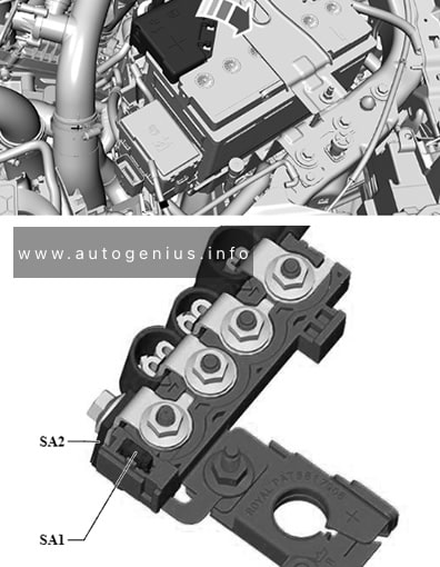
| R1 | Relay for reducing agent metering system (diesel) Relay for gas shut-off valves (with natural gas engine) |
|
| R2 | Washer pump relay | |
| R3 | Terminal 15 voltage supply relay | |
| R4 | Terminal 75x voltage supply relay | |
| R5 | – | |
| R6 | – |
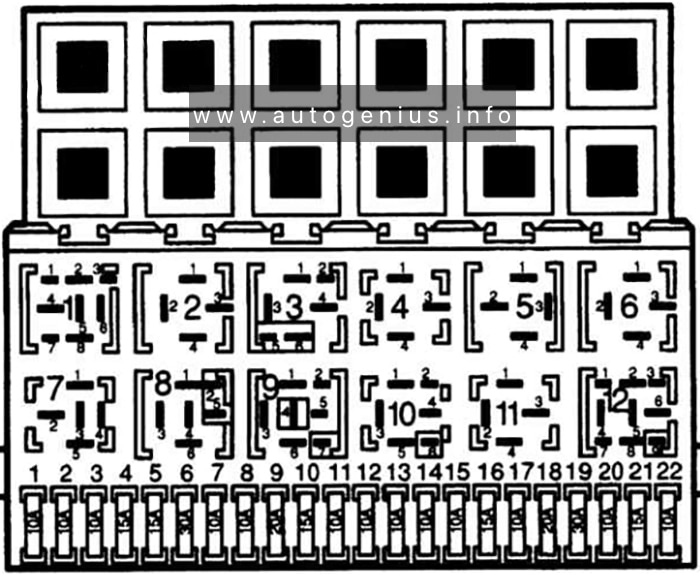
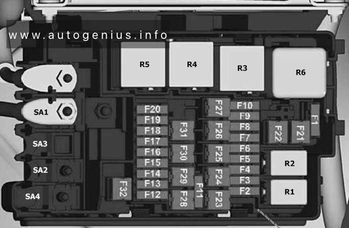
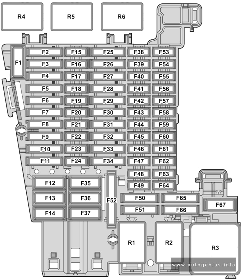
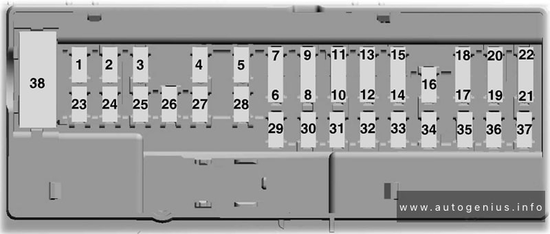
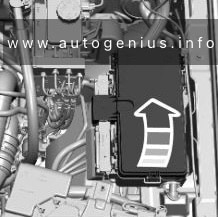
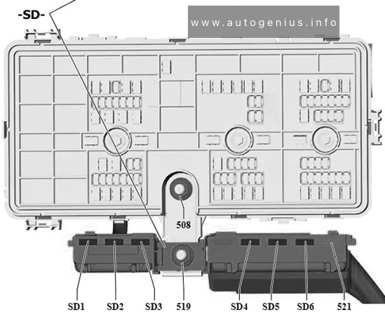
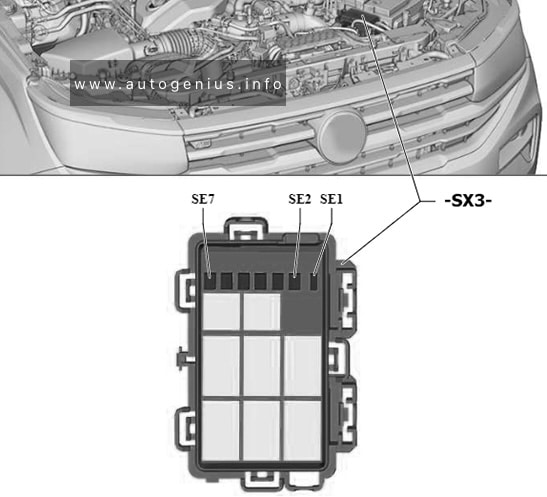
Engine Compartment Fuse Box
Fuse Box Diagram
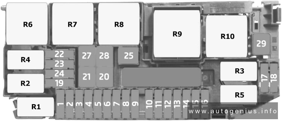
Assignment of the fuses in the engine compartment
| № | Amps | Function / component |
|---|---|---|
| F1 | 10 A / 15 A / 30 A | Engine/motor control unit |
| F2 | 7.5 A / 10 A | Fuel pressure sender for low pressure (2.0l petrol) Activated charcoal filter solenoid valve 1 (2.0l petrol) Camshaft control valve 1 (2.0l petrol) Exhaust camshaft control valve 1 (2.0l petrol) Charge air cooling pump (1.6l diesel) Fuel pressure regulating valve Valve for oil pressure control (1.6l diesel) Coolant valve for cylinder head (1.6l diesel) Coolant pump for high-temperature circuit (1.6l diesel) Auxiliary pump for heating (2.0l petrol) |
| F3 | 15 A | Lambda probe 1 before catalytic converter Lambda probe 1 after catalytic converter Control unit for NOx sender (1.6l diesel) Control unit 2 for NOx sender (1.6l diesel) |
| F4 | 15 A | Fuel pump control unit (For petrol engine with forced induction) Fuel pump relay (For petrol engine with no forced induction) Engine component current supply relay |
| F5 | 7.5 A / 10 A / 15 A | Radiator fan (For petrol engine with forced induction) Activated charcoal filter solenoid valve 1 Camshaft control valve 1 Turbocharger air recirculation valve (2.0l petrol) Intake manifold flap valve (2.0l petrol) Exhaust camshaft control valve 1 (For petrol engine with forced induction) Valve for oil pressure control (For petrol engine with forced induction) Piston cooling jet control valve (2.0l petrol) Inlet camshaft control valve 1 Oil level and oil temperature sender (2.0l petrol, 1.6l diesel) High-pressure valve for gas mode Charge pressure control solenoid |
| F6 | 20 A / 7.5 A | Ignition coils 1-3 with output stage Automatic glow period control unit Heater element for crankcase breather (1.6l diesel) |
| F7 | 15 A / 10 A | Vacuum pump for brakes (2.0l petrol) Coolant shut-off valve (2.0l petrol) Coolant valve for gearbox |
| F8 | 10 A | Fuel pump relay (For petrol engine with no forced induction) Injector, cylinders 1-3 (For petrol engine with no forced induction) Gas injection valve 1-3 (with natural gas engine) Injector 2, cylinders 1-4 (2.0l petrol) Exhaust cam actuator A for cylinders 1-4 (2.0l petrol) Exhaust cam actuator B for cylinders 1-4 (2.0l petrol) |
| F9 | 7.5 A | Brake light switch |
| F10 | 7.5 A | Battery monitor control unit Onboard supply control unit Data bus diagnostic interface |
| F11 | 30 A | Auxiliary hydraulic pump 1 for gearbox oil |
| F12 | 10 A | Magnetic clutch relay |
| F13 | – | – |
| F14 | 7.5 A | Engine/motor control unit ABS control unit Main relay |
| F15 | 30 A / 15 A | Mechatronic unit for dual clutch gearbox |
| F16 | – | – |
| F17 | 7.5 A | Engine/motor control unit |
| F18 | 30 A | Starter |
| F19 | – | – |
| F20 | 40 A / 60 A | ABS control unit |
| F21 | 25 A | ABS control unit |
| F22 | – | – |
| F23 | – | – |
| F24 | 30 A | Radiator fan thermal switch |
| F25 | 20 A / 40 A | Radiator fan (For petrol engine with no forced induction) Auxiliary air heater element (1.6l diesel) |
| F26 | 50 A | Radiator fan (For petrol engine with forced induction) |
| F27 | 30 A / 40 A | Radiator fan (For petrol engine with no forced induction) Auxiliary air heater element (1.6l diesel) |
| F28 | 40 A | Auxiliary air heater element (1.6l diesel) |
| F29 | – | – |
| R1 | Fuel pump relay (petrol) Engine component current supply relay (2.0l petrol) |
|
| R2 | Magnetic clutch relay | |
| R3 | Starter relay 2 | |
| R4 | Vacuum pump relay (1.5l petrol) | |
| R5 | Starter relay 1 | |
| R6 | Main relay (petrol) Terminal 30 voltage supply relay (diesel) |
|
| R7 | Radiator fan 2nd speed relay (petrol) High heat output relay (diesel) |
|
| R8 | Radiator fan relay (petrol) Low heat output relay (diesel) |
|
| R9 | Automatic glow period control unit (diesel) | |
| R10 | – |
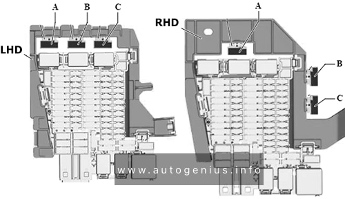
WARNING: Terminal and harness assignments for individual connectors will vary depending on vehicle equipment level, model, and market.