Audi 200 (C3; 1983 – 1991) – fuse and relay box diagram
Year of production: 1983, 1984, 1985, 1986, 1987, 1988, 1989, 1990, 1991
This article covers the second-generation Audi 200 (C3), produced from 1983 to 1991. It includes fuse box diagrams for the 1983, 1984, 1985, 1986, 1987, 1988, 1989, 1990 and 1991 models, provides details on the location of the fuse panels inside the vehicle, and explains the function and layout of each fuse.
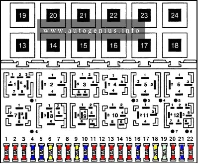
Fuses box diagram

Assignment of the fuses in the fuse box
| № |
A |
Description |
| 1 | 15 | Fog lights, rear fog lights |
| 2 | 15 | Emergency flashers |
| 3 | 25 | Horn, brake lights |
| 4 | 15 | Reading lights, luggage compartment, cigar lighter, interior lights, make-up mirror, Board Computer |
| 5 | 30 | Not used |
| 6 | 5 | Side marker, park lights, right |
| 7 | 5 | Side marker, park lights, left |
| 8 | 10 | Hi-beam headlight, hi-beam indicator light |
| 9 | 10 | Hi-beam headlight, left |
| 10 | 10 | Low beam, headlight, right |
| 11 | 10 | Low beam, headlight, left |
| 12 | 15 | Instrument cluster, back-up lights, cruise control, electronic thermoswitch |
| 13 | 15 | Fuel pump |
| 14 | 5 | Glove compartment, engine compartment, license plate lights |
| 15 | 25 | Windshield wipers |
| 16 | 30 | Rear window heat element, outside mirror heat element |
| 17 | 30 | Fresh air blower |
| 18 | 5 | Rear wiper (wagon) |
| 19 | 10 | Central locking system and fuel injection control unit 100, 100 Quattro |
| 20 | 30 | Heated seats with Memory Seat |
| 21 | 25 | Not used |
| 22 | – | Not used |
| 23 | 30 | Not used |
| 24 | 10 | Not used |
| 25 | 30 | Power seats with memory, passenger power seat |
| 26 | 5 | Auto-Check, power mirrors, driver’s seat memory control |
| 27 | 10 | Ignition control unit 100, 100 Quattro |
| 28 | 15 | Fuel injection control unit II |
| 29 | – | Spare fuses |
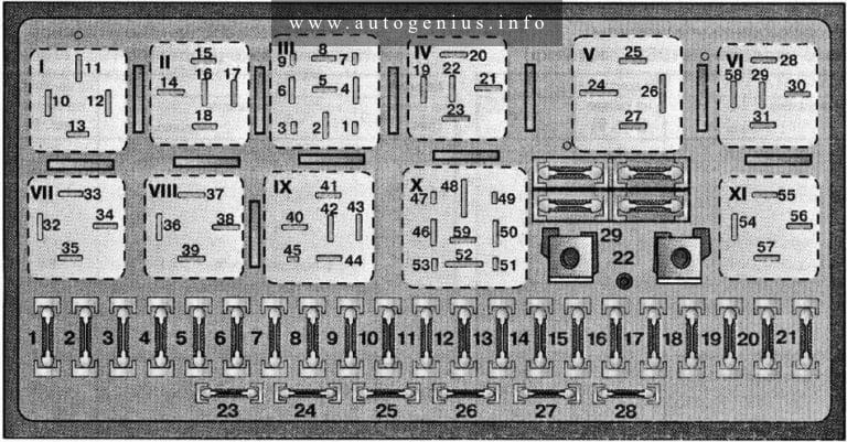
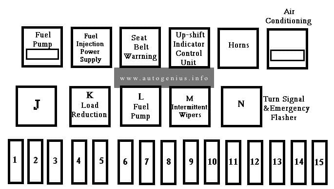
Relay box diagram
Assignment of the relays in the relay box
| № | Description |
| 1 | Open |
| 2 | Radiator cooling fan (stage 2) |
| 3 | 100 models — radiator cooling fan after-run 200 models — radiator cooling fan (stage 1) |
| 4 | Not used |
| 5 | Load reduction relay |
| 6 | Not used |
| 7 | Horn |
| 8 | Anti-theft relay |
| 9 | Intermittent washer/wiper |
| 10 | Fuel pump |
| 11 | A/C relay |
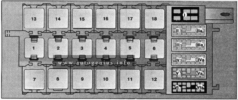
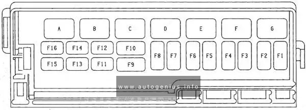
Auxiliary relay panel
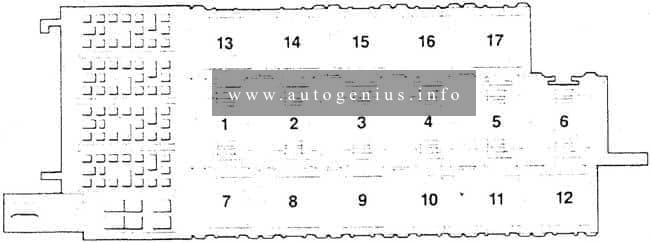
Assignment of the relay in the auxiliary relay box
| № |
Description |
| 1 | Open |
| 2 | Seat belt/park light radio warning control unit |
| 3 | Interior light delay control unit |
| 4 | Open |
| 5 | Lamp control unit, front |
| 6 | Open |
| 7 | Rad coolant fan relay 3rd stage |
| 8 | ABS combination relay |
| 9 | Intensive washer relay |
| 10 | Power window control unit |
| 11 | Power window control unit |
| 12 | Rear window wiperwasher relay |
| 13 | Open |
| 14 | Circuit breaker for windows |
| 15 | Driver heated seat relay |
| 16 | Passenger heated seat relay |
| 17 | Open |
WARNING: Terminal and harness assignments for individual connectors will vary depending on vehicle equipment level, model, and market.