Chery A113 (2007 – 2015) – fuse and relay box diagram
Year of production: 2007, 2008, 2009, 2010, 2011, 2012, 2013, 2014, 2015
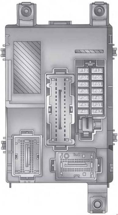
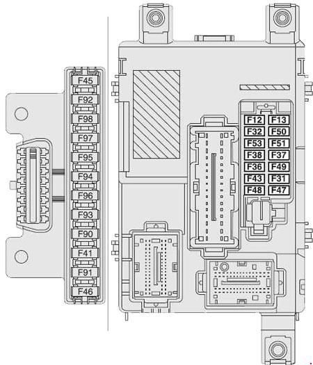
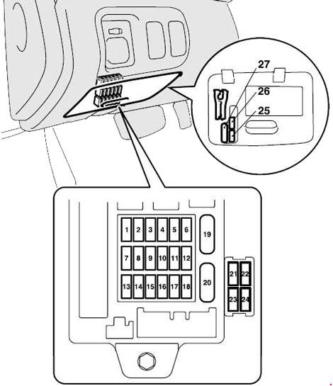
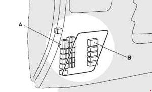
The instrument panel fuse panel
Fuse Box Location
The instrument fuse box is located within the left cover plate of the dashboard.
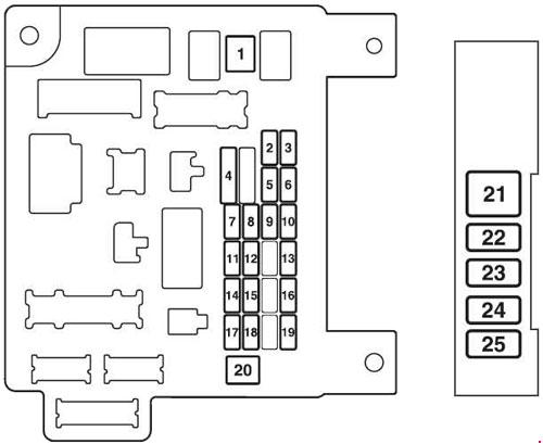
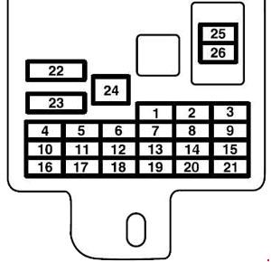
Fuse Box Diagram
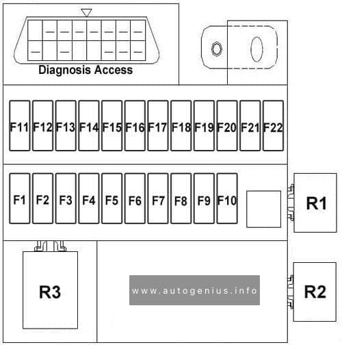
Assignment of the fuses in the instrument panel
| No. |
A |
Function/component |
| F1 | 10 | Combined instruments |
| F2 | 10 | Rear view mirror, brake switch, BCM |
| F3 | 10 | ABS control |
| F4 | 10 | Air Bag |
| F5 | – | Not used |
| F6 | 15 | Washer, rear wiper power supply, sunroof control |
| F7 | 10 | Steering power supply, A/C relay coil |
| F8 | 15 | Front wiper |
| F9 | 15 | Cigarette lighter |
| F10 | 10 | Radio/player control |
| F11 | – | Not used |
| F12 | 25 | Start |
| F13 | 10 | Diagnosis Access |
| F14 | 10 | Braking Lamp |
| F15 | 20 | Audio device |
| F16 | 15 | Horn, fog lamp |
| F17 | – | Not used |
| F18 | 10 | Clearance lamp, ceiling lamp |
| F19 | 15 | Alarm switch |
| F20 | 10 | Lamp switch, instrument |
| F21 | 20 | Sunroof power supply |
| F22 | 20 | Rear defroster |
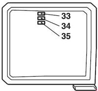
| Relay | ||
| R1 | Blower Relay | |
| R2 | Steering relay | |
| R3 | Front wiper relay | |
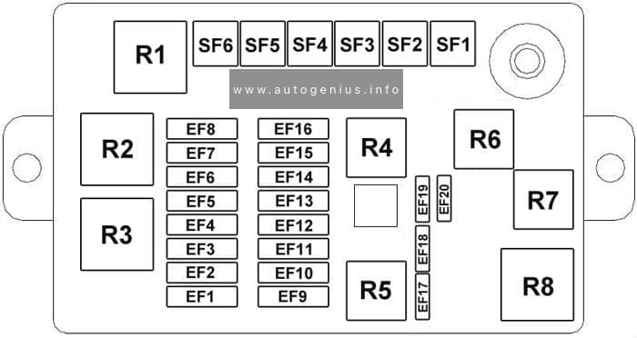
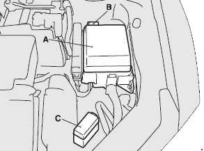
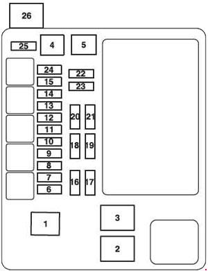
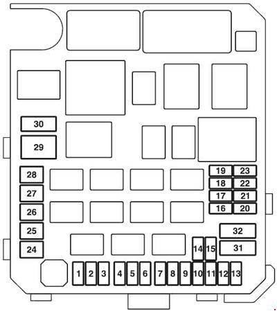
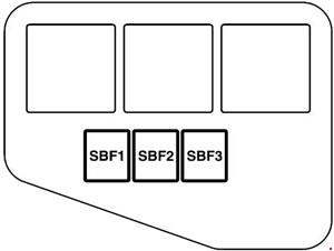
Engine compartment fuse box
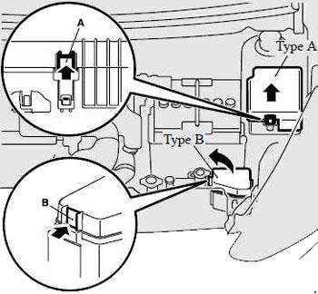
Fuse Box Location
The fuse box is located near the front compartment battery.
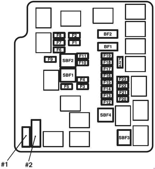
Fuse Box Diagram

Assignment of the fuses in the engine compartment
| No. |
A |
Function/component |
| SF1 | 30 | Fan. high speed |
| SF2 | 30 | BCM |
| SF3 | 30 | A/C |
| SF4 | 40 | Instrument electric |
| SF5 | 30 | ABS |
| SF6 | 30 | ABS |
| EF1 | 20 | Fan. low speed |
| EF2 | 15 | Front fog lamp |
| EF3 | 10 | ECU |
| EF4 | 15 | Fuel pump |
| EF5 | 30 | Primary relay |
| EF6 | 10 | Compressor |
| EF7 | 15 | Oxygen sensor |
| EF8 | – | Not used |
| EF9 | 15 | Ignition coil |
| EF10 | 10 | Backup lamp |
| EF11 | 10 | Right position lamp |
| EF12 | 10 | Left position lamp |
| EF13 | 10 | Right high beam |
| EF14 | 10 | Left high beam |
| EF15 | 10 | Right low beam |
| EF16 | 10 | Left low beam |
| EF17 | 10 | Spare |
| EF18 | 10 | Spare |
| EF19 | 10 | Spare |
| EF20 | 10 | Spare |
| Relay | ||
| R1 | Front Fog Lamp Relay | |
| R2 | Fan High Speed Relay | |
| R3 | Fan Low Speed Relay | |
| R4 | Low Beam Relay | |
| R5 | Compressor | |
| R6 | High Beam Relay | |
| R7 | Main relay | |
| R8 | Electric Fuel Pump | |
WARNING: Terminal and harness assignments for individual connectors will vary depending on vehicle equipment level, model, and market.