Volkswagen Polo (6R/MK5; 2009 – 2017) – fuse and relay box diagram
Year od production: 2009, 2010, 2011, 2012, 2013, 2014, 2015, 2016, 2017
This article focuses on the fifth-generation Volkswagen Polo (6R/6C/61), produced from 2009 to 2018. It includes fuse box diagrams for models from 2009 to 2017, provides information on the location of the fuse panels inside the vehicle, and details the fuse and relay assignments (fuse layout).
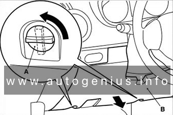
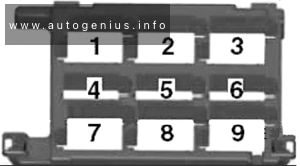
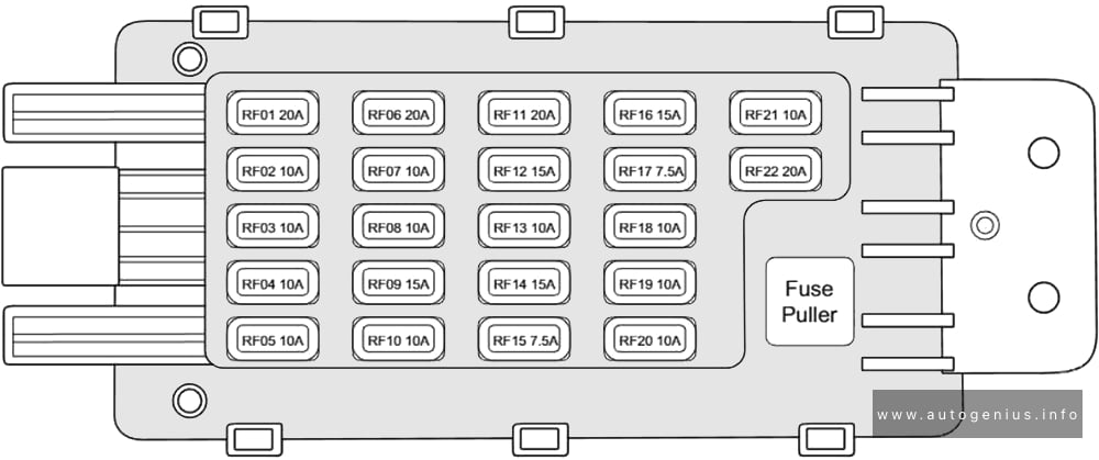
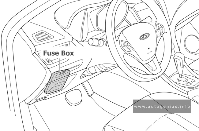
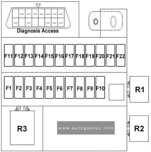
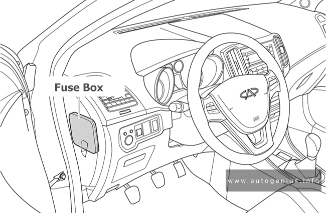
Passenger Compartment Fuse Box
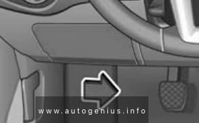
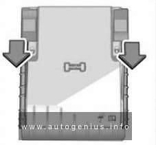
Fuse Box Location
The fuse box is located behind the cover below the steering wheel.
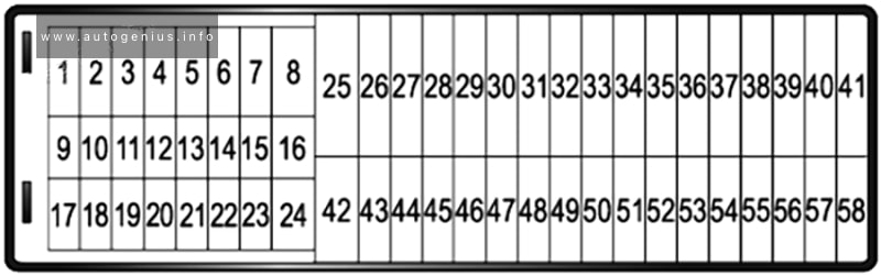
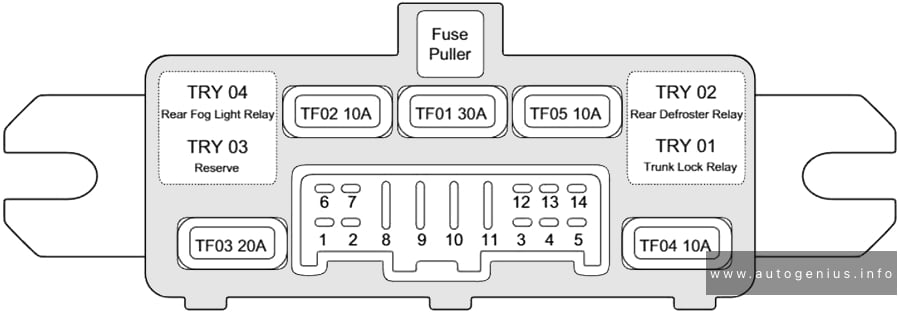
Fuse Box Diagram
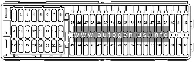
Assignment of the fuses in the passenger compartment
| № | Amp | Component |
|---|---|---|
| F1 | 5A | Control unit in dash panel insert ABS control unit Mobile telephone operating electronics control unit |
| F2 | 10A | Steering column combination switch On-board supply control unit Rear window wiper motor Windscreen and rear window washer pump |
| F3 | 5A | Fuel pump relay Engine control unit Fuel supply relay Fuel pump control unit Control unit for structure-borne sound |
| F4 | 2A | (2A) Combination switch |
| F5 | – | – |
| F6 | 5A | Instrumentation control module |
| F7 | 5A | Headlight range control regulator Number plate left light Number plate right light On-board supply control unit |
| F8 | 10A | Engine management system |
| F9 | 5A/7.5A | TCS and ESP button Tyre pressure monitor display button Steering angle sender ABS control unit Stop/start system button Data bus diagnostic interface |
| F10 | 5A | Cruise control system switch Steering column combination switch Brake light switch Clutch pedal switch On-hoard supply control unit |
| F11 | 5A/10A | Headlight range control regulator Left headlight range control motor Right headlight range control motor Cruise control system switch On-hoard supply control unit Cornering light and headlight range control unit |
| F12 | 5A | Door mirror adjustment switch |
| F13 | 5A | Transmission control module (TCM) |
| F14 | 5A | Supplementary restraint system (SRS) control module |
| F15 | 5A | Heated windscreen waterjets |
| F16 | 5A | Parking aid control module |
| F17 | – | – |
| F18 | 5A | Rear fog light cut-out contact switch Control unit in dash panel insert Rear left fog light bulb On-board supply control unit |
| F19 | 5A | Multifunction control module |
| F20 | 5A | Steering angle sender Control unit in dash panel insert Fuel supply relay Terminal 30 voltage supply relay Low heat output relay High heat output relay |
| F21 | 10A | Multifunction control module |
| F22 | 5A | Diagnostic connection Climatronic control unit Air conditioning system control unit Mobile telephone operating electronics control unit Ignition key withdrawal lock solenoid |
| F23 | 5A | Selector lever Rain sensor On-hoard supply control unit Engine control unit Data bus diagnostic interface |
| F24 | 5A | On-board supply control unit Driver side heated exterior mirror Front passenger side heated exterior mirror |
| F25 | 5A | High pressure sender Heater control unit Radiator fan control unit Air conditioning system control unit Trailer detector control unit Diagnostic connection Humidity sender Radiator fan control unit Voltage stabiliser Voltage stabiliser 2 |
| F26 | 7,5A | Air mass meter Oil level and oil temperature sender Power steering control unit Heater element for crankcase breather Starter relay 1 Starter relay 2 |
| F27 | 7,5A | Reversing lamps |
| F28 | 10A | Engine management system |
| F29 | 10A | Engine management system |
| F30 | 10A | Engine management system |
| F31 | 5A/10A | Engine management system |
| F32 | 10A/15A/20A/30A | Engine management system |
| F33 | 5A | Clutch position sender Brake light switch |
| F34 | 15A | Control unit in dash panel insert Left main beam bulb Right main beam bulb On-board supply control unit Left gas discharge light control unit Right gas discharge light control unit |
| F35 | 15A/20A | Engine management system |
| F36 | 7,5A | Right main beam bulb |
| F37 | 25A | Seat heater control module |
| F38 | 30A | Transmission control module (TCM) |
| F39 | 10A/15A | Right dipped beam bulb |
| F40 | 30A | AC/heater blower control module |
| F41 | 10A | Rear screen wiper motor |
| F42 | 15A | Cigarette lighter 12 V socket |
| F43 | 15A | Multifunction control module |
| F44 | 5A | Alarm system |
| F45 | 15A | Audio system |
| F46 | 20A | Head lamp washers |
| F47 | 20A | On-board supply control unit Windscreen wiper motor |
| F48 | 25A | Multifunction control module |
| F49 | 15A/30A | Fuel pump relay Fuel supply relay |
| F50 | 25A | Door function control module, driver |
| F51 | 25A | Door function control module, passenger |
| F52 | 30A | Rear left door control unit Rear right door control unit |
| F53 | 30A | Multifunction control module |
| F54 | 15A | Front fog lamps |
| F55 | 15A/20A | Engine management system |
| F56 | 15A | Day time running lamps |
| F57 | 15A | Multifunction control module |
| F58 | 20A | Brake servo vacuum pump |
| F59 | 10A/15A | Left dipped beam bulb |
| F60 | 15A | Audio system |
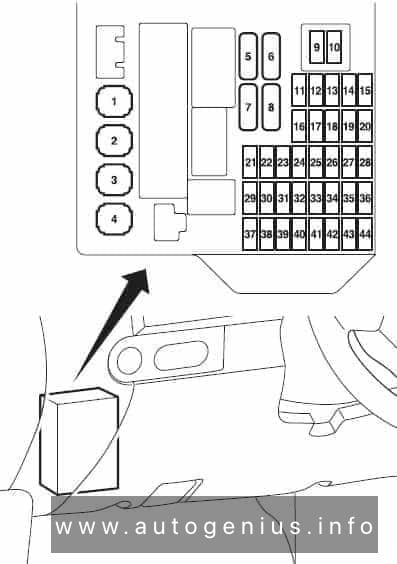
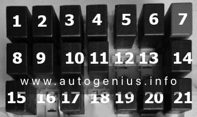
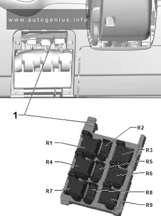
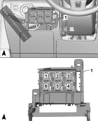
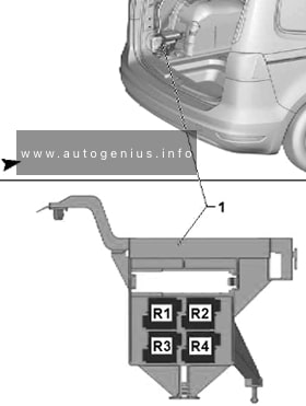
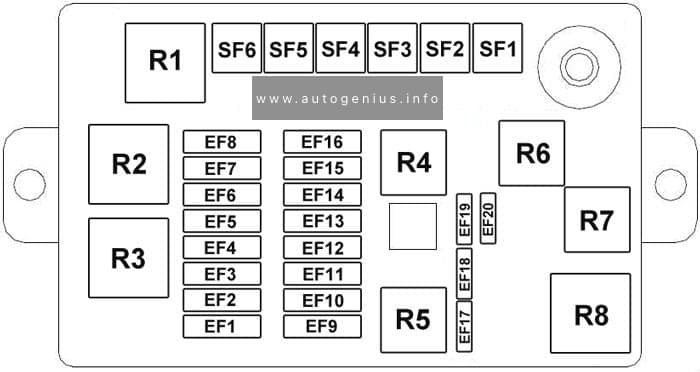
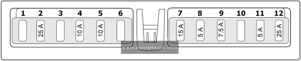
The onboard supply control unit
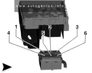
Fuse Box Location
The fuse/relay panel located on left underneath the dashboard.
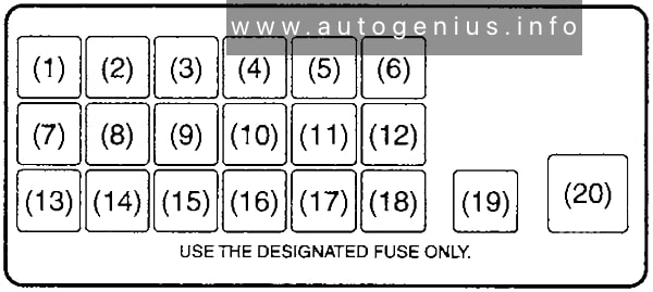
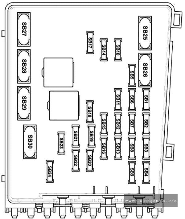
Fuse Box Diagram
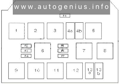
Assignment of the fuses in the passenger compartment (onboard supply control unit)
| № | Amp | Component |
|---|---|---|
| 1 | ||
| 2 | ||
| 3 | Ignition main circuits relay | |
| 4a | Headlamp low beam relay | |
| 4b | Fuel system primer relay | |
| 5 | ABS protection relay | |
| 6 | Petrol: Fuel pump (FP) relay | |
| 7 | Starter motor inhibit relay | |
| 8 | Ignition auxiliary circuits relay | |
| 9 | Headlamp washer pump relay | |
| 10 | Ignition auxiliary circuits relay (08.09) | |
| 11 | ||
| 12 | ||
| 13a | Starter motor relay | |
| 13b | Auxiliary heater relay | |
| F1 | 30A | Sunroof control module |
| F2 | 40A | Engine coolant heater |
| F3 | 40A | Engine coolant heater |
| F4 | 40A | Engine coolant heater |
| F5 | 20A | Trailer control module |
| F6 | 20A | Trailer control module |
| F7 | 15A | Trailer control module |
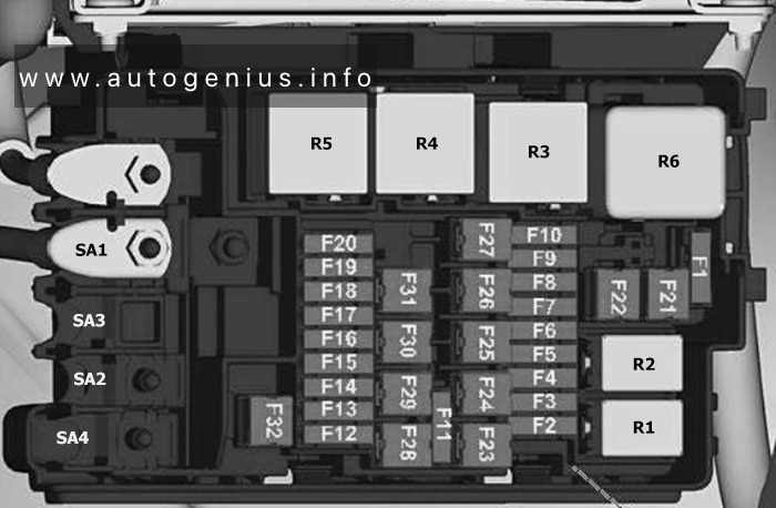
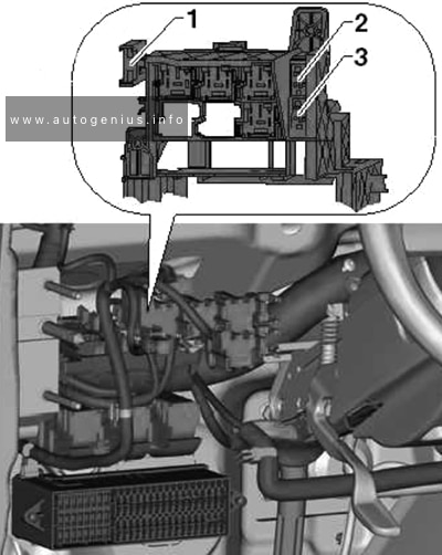
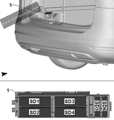
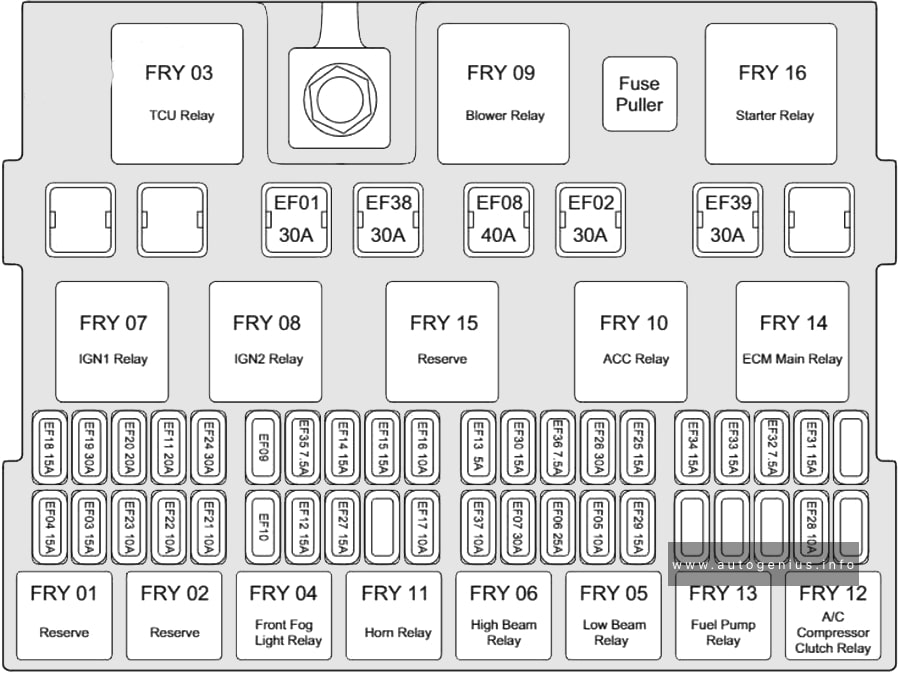
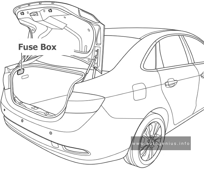
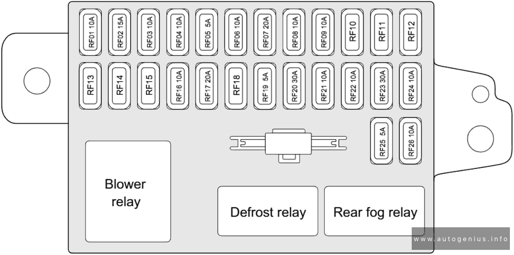
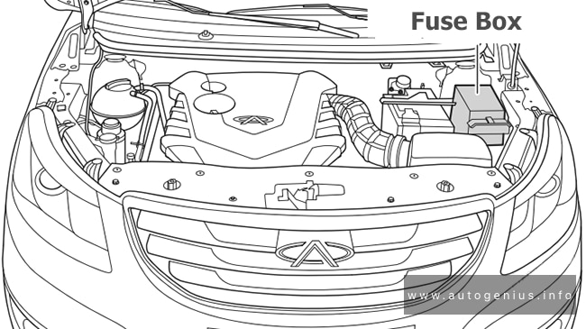
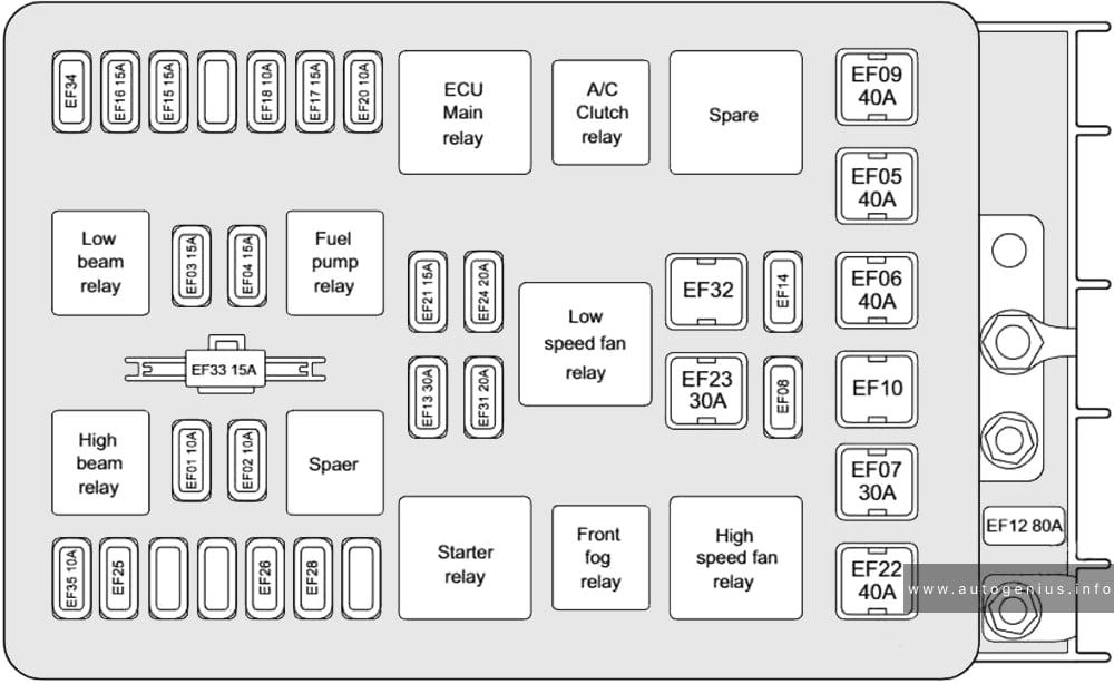
Engine Compartment Fuse Box
Fuse Box Location
It is located in the engine compartment on the battery.
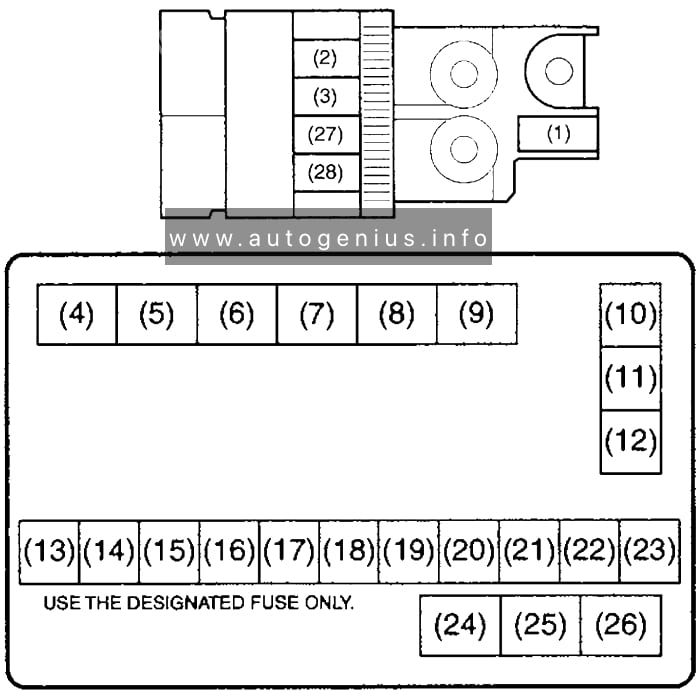
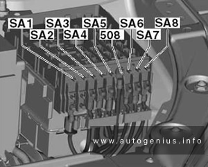
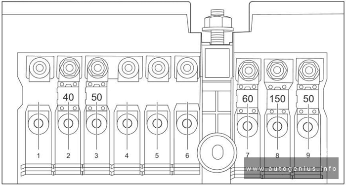
Fuse Box Diagram (Main fuse box)
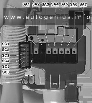
Assignment of the fuses in the engine compartment (main fuse box)
| № | Amp | Component |
|---|---|---|
| SA1 | 150A/175A | Alternator |
| SA2 | 30A | Gas fuel control module |
| SA3 | 110A | |
| SA4 | 50A | Power steering control module |
| SA5 | 40A | ABS control module |
| SA6 | 40A | Engine coolant blower motor control module |
| SA7 | 50A | Glow plugs |
| SC1 | 25A | ABS control module |
| SC2 | 30A | Engine coolant blower motor control module |
| SC3 | 5A | Engine coolant blower motor control module |
| SC4 | 10A | ABS control module |
| SC5 | 5A | Multifunction control module |
| SC6 | 30A | Transmission control module (TCM) |
WARNING: Terminal and harness assignments for individual connectors will vary depending on vehicle equipment level, model, and market.