Holden Commodore (VF; 2013 – 2017) – fuse box diagram
Year of production: 2013, 2014, 2015, 2016, 2017
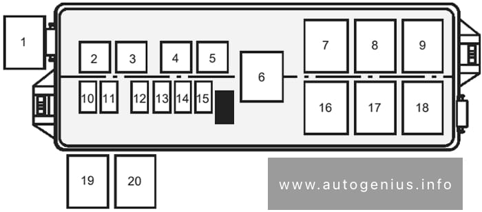
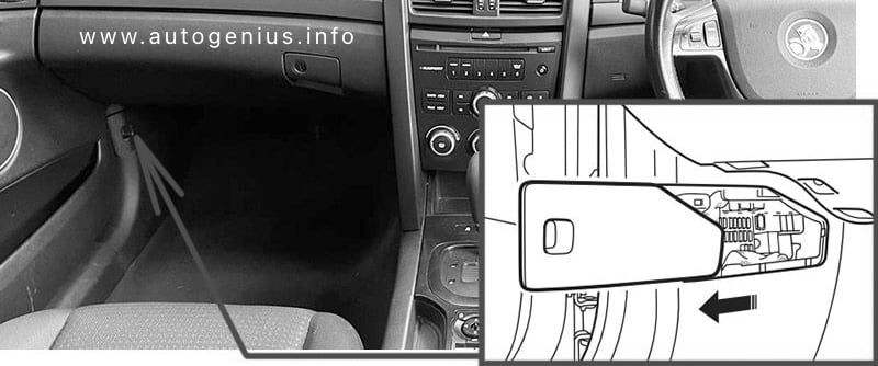
Passenger Compartment Fuse Box
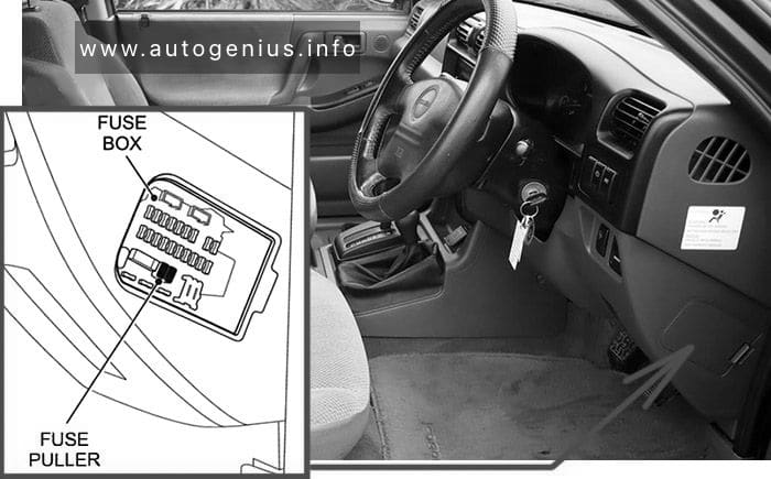
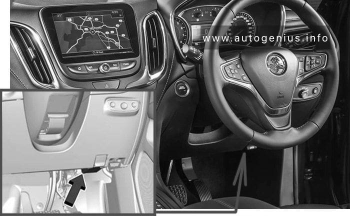
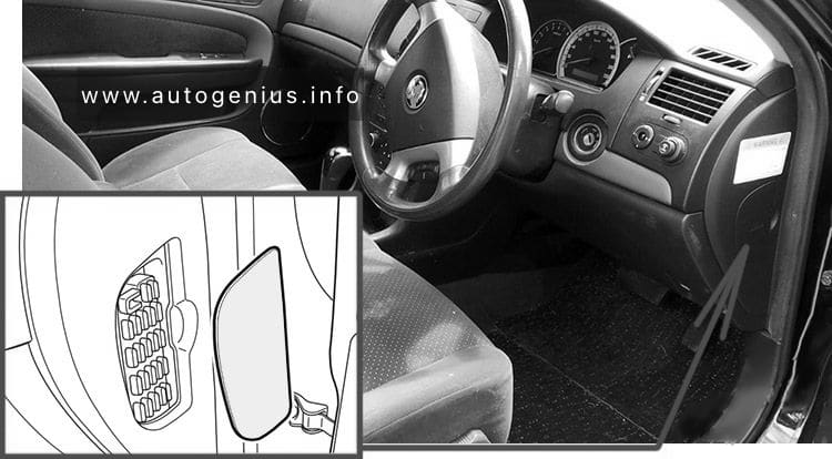
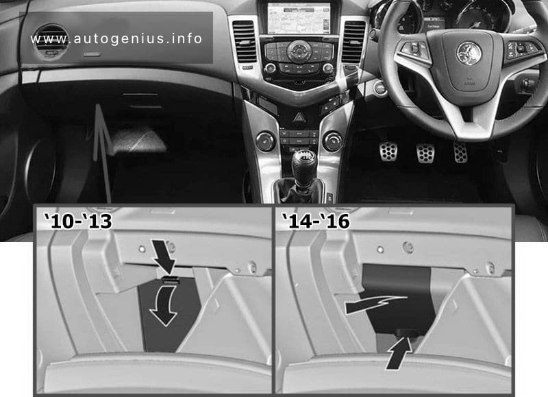
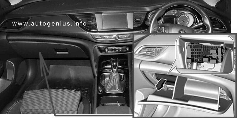
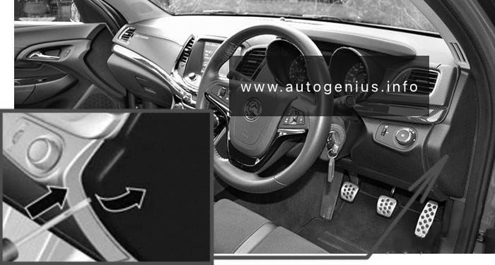
Fuse Box Location
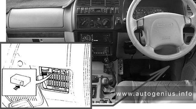
Insert a screwdriver in the slot indicated and lever off the fuse panel cover.
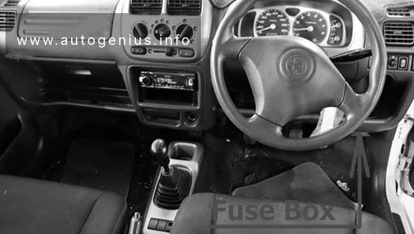
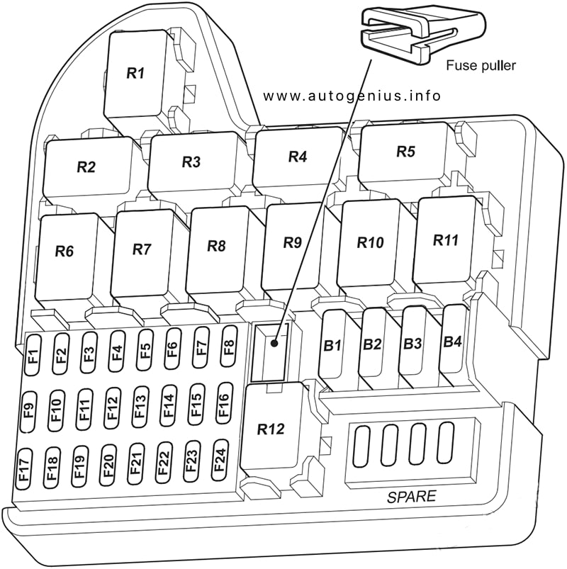
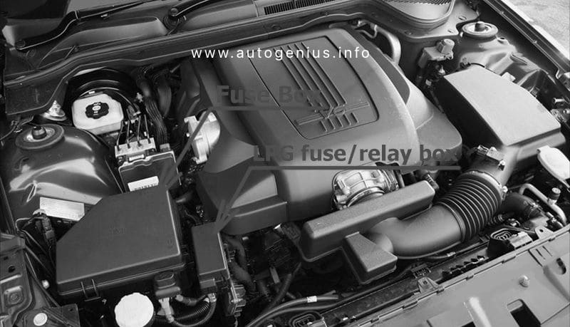
Holden Commodore (VF; 2013 – 2017)- fuse box location – passenger compartment To help in replacing fuses, there is a special fuse gripping tool located beside the spare fuses in the fuse box.
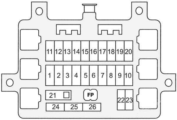
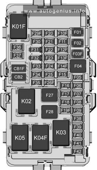
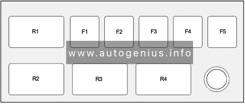
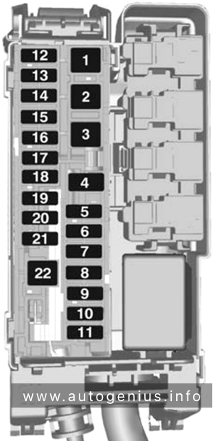
Fuse Box Diagram
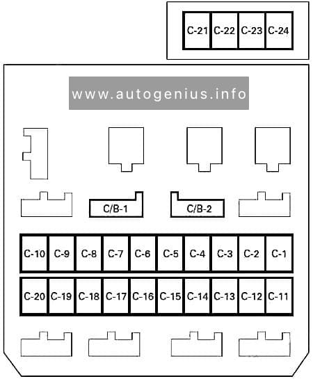
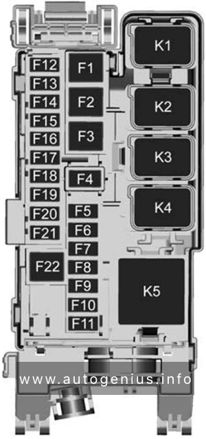
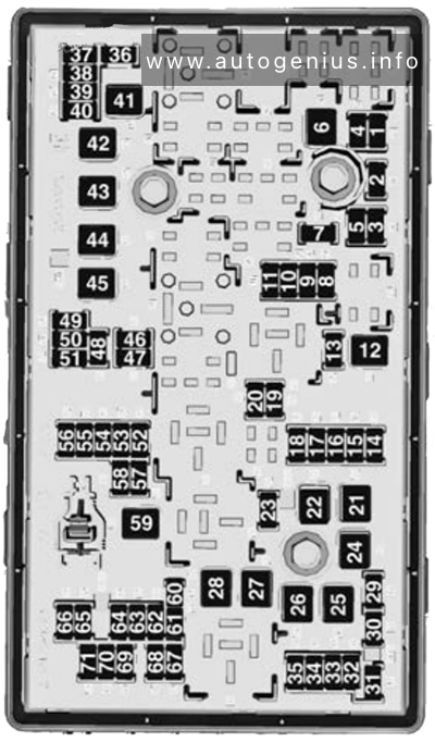
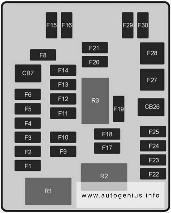
Holden Commodore (VF; 2013 – 2017)- fuse box diagram – passenger compartment
№
Amps
Function
F1
15A
BODY CONTROL MODULE 1
F2
10A
DIAGNOSTIC CONNECTOR
F3
30A
2013-2015: LPG SHUT-OFF SOLENOID
F4
15A
BODY CONTROL MODULE 2
F5
2A
IGNITION SWITCH
F6
15A
ELECTRIC STEERING CONTROL LOCK
CB7
–
–
F8
–
–
F9
–
–
F10
–
–
F11
30A
SHUNT 1
F12
10A
AIRBAG / AOS
F13
15A
INSTRUMENT CLUSTER
F14
15A
HVAC CONTROL MODULE
F15
10A
RAIN SENSOR
F16
15A
BODY CONTROL MODULE
F17
15A
2013-2015: LPG SHUT-OFF SOLENOID
F18
–
–
F19
2A
SWC BACKLIGHT
F20
–
–
F21
–
–
F22
30A
SHUNT 2
F23
15A
BODY CONTROL MODULE
F24
15A
BODY CONTROL MODULE
F25
10A
BODY CONTROL MODULE
CB26
–
–
F27
30A
BODY CONTROL MODULE 8
F28
40A
BLOWER FAN
F29
15A
ACCESSORIES
F30
15A
BODY CONTROL MODULE 7
Relays
R1
LOGISTICS MODE
R2
2013-2015: LPG SHUT-OFF SOLENOID
R3
2013-2015: LPG SHUT-OFF SOLENOID
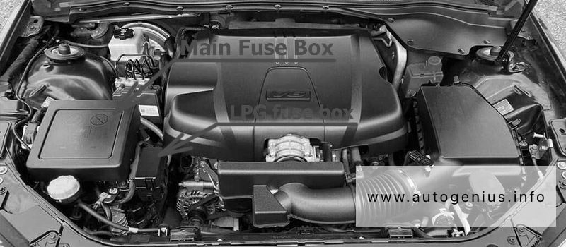
Engine Compartment Fuse Box
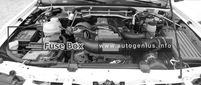
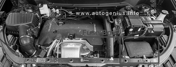
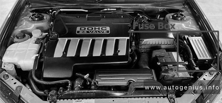
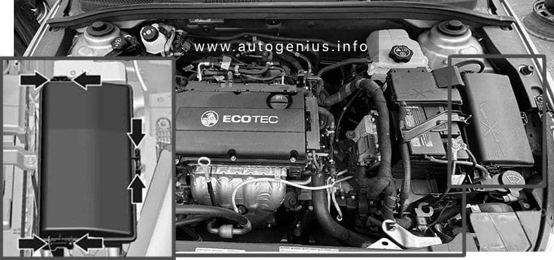
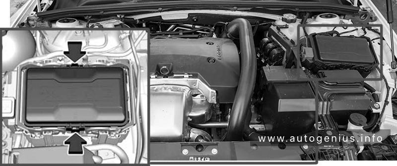
Fuse Box Location
Remove the clip-on cover to access.
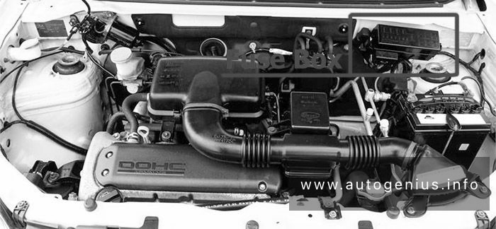
Holden Commodore (VF; 2013 – 2017)- fuse box location – engine compartment To help in replacing fuses, there is a special fuse gripping tool located beside the spare fuses in the fuse box.
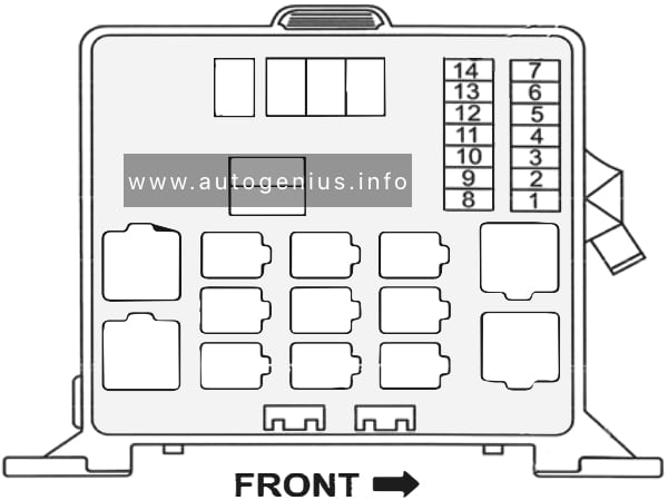
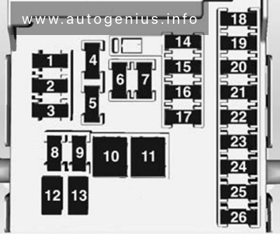
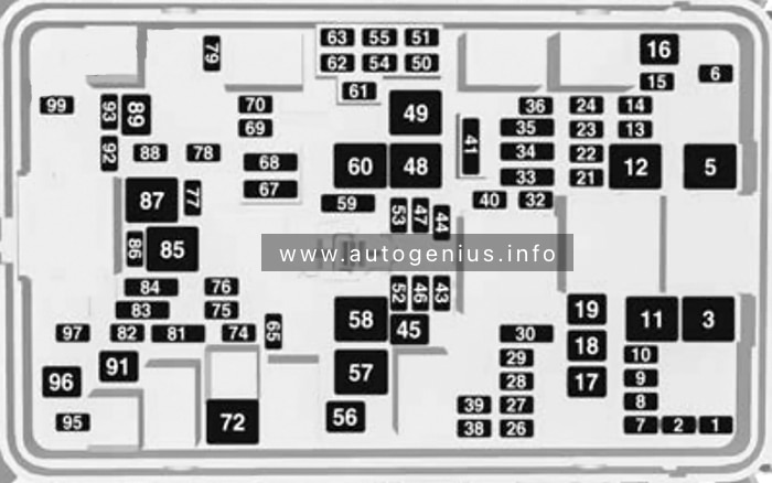
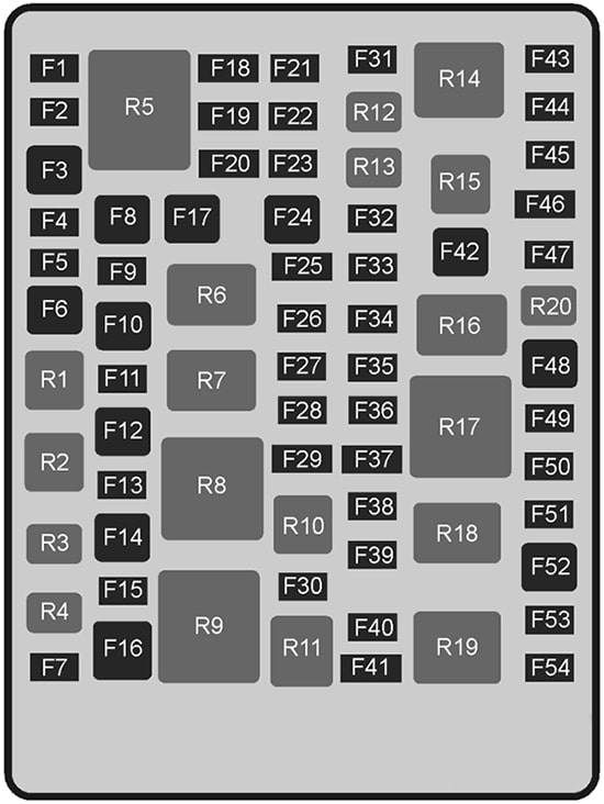
Fuse Box Diagram
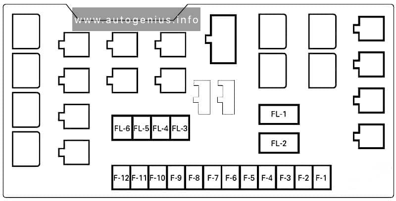
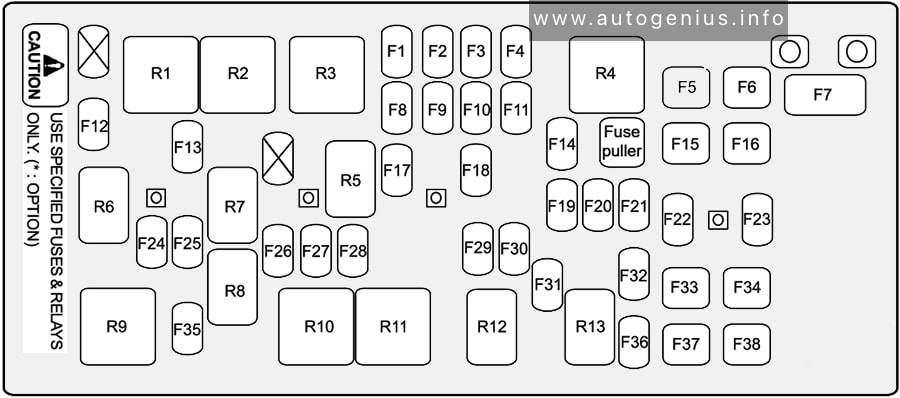
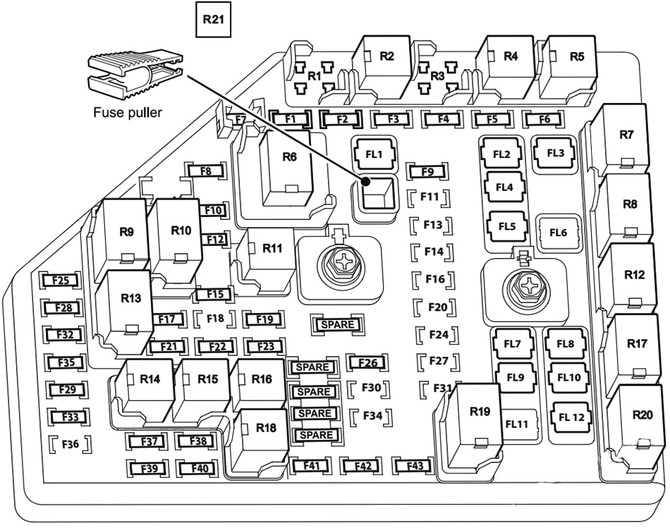
Holden Commodore (VF; 2013 – 2017)- fuse box diagram – engine compartment
№
Amps
Function
F1
10A
HEATED MIRRORS
F2
–
–
F3
30A
REAR DEMISTER
F4
–
–
F5
15A
SPOT LAMP RH
F6
30A
DRIVER POWER SEAT
F7
20A
WASHER PUMP
F8
30A
PASSENGER POWER SEAT
F9
15A
EMER / VEH / FT / LP
F10
–
–
F11
20A
DRIVING LAMPS
F12
25A
HEADLAMP WASHER
F13
15A
SPOT LAMP LH
F14
60A
ABS PUMP
F15
30A
ABS VALVES
F16
–
–
F17
–
–
F18
15A
HEATED FRONT SEATS
F19
–
–
F20
–
–
F21
7.5A
FRONT PASSENGER WINDOW SWITCH
F22
20A
REAR WIPER
F23
20A
SUNROOF
F24
30A
FRONT WIPERS
F25
5A
AOS IGN / IPC IGN
F26
20A
LRBEC IGN
F27
–
–
F28
20A
IGN / INJ EVEN (V8)
F29
15A
ECM (V8), INJ / IGN ODD (V6) / EMIS 1
F30
–
–
F31
–
–
F32
15A
FOG LAMPS
F33
10A
IGNITION-IP / BODY
F34
10A
FUEL SYSTEM CONTROL MODULE
F35
–
–
F36
15A
ESCL
F37
15A
EMIS 2 / IGN EVEN (V6)
F38
20A
ECM (V6), INJ / IGN ODD (V8)
F39
10A
INCLR PUMP
F40
–
–
F41
15A
TRANSMISSION CONTROL MODULE / ELECTRIC POWER STEERING
F42
30A
STARTER MOTOR
F43
–
–
F44
15A
LH HID HEADLAMP
F45
15A
RH HID HEADLAMP
F46
10A
LH & RH HI BEAM HEADLAMP
F47
15A
HORN
F48
60A
ENGINE COOLING FAN
F49
10A
AUTOMATIC HEADLAMP LEVELLING
F50
15A
TRANSMISSION CONTROL MODULE IGN
F51
15A
ENGINE CONTROL MODULE IGN
F52
30A
BRAKE VACUUM PUMP
F53
10A
AIR CONDITIONING CLUTCH
F54
10A
VAPORISER CONTROL MODULE
Relays
R1
DRIVING LAMPS
R2
HEADLAMP WASHER
R3
REAR WASHER PUMP
R4
FRONT WASHER PUMP
R5
REAR DEMISTER
R6
FRONT WIPER CONTROL
R7
WIPER SPEED
R8
ENGINE CONTROL MODULE
R9
–
R10
INCLR PUMP
R11
–
R12
REAR WIPER CONTROL
R13
FOG LAMPS
R14
LOW BEAM HEADLAMPS
R15
HIGH BEAM HEADLAMPS
R16
STARTER
R17
RUN/CRANK
R18
BRAKE VACUUM PUMP
R19
AIR-CONDITIONING CONTROL
R20
HORN
Note: Relays R3, R4, R12, R13 and R20 are PCB mounted relays.
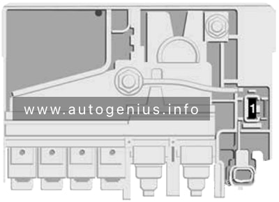
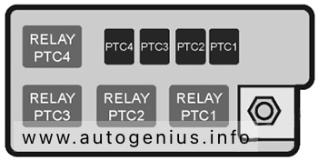
LPG fuse/relay box (If available)
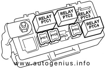
Holden Commodore (VF; 2013 – 2017)- fuse box diagram – engine compartment (LPG fuse and relay box)
№
Amps
Function
PTC1
40A
VAPORISER HEATER 1
PTC2
40A
VAPORISER HEATER 2
PTC3
–
SPARE
PTC4
40A
VAPORISER HEATER 3
Relays
PTC1
VAPORISER HEATER 1
PTC2
VAPORISER HEATER 2
PTC3
SPARE
PTC4
VAPORISER HEATER 3
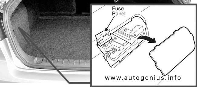
Luggage Compartment Fuse Box
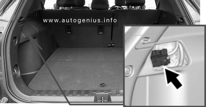
Fuse Box Location
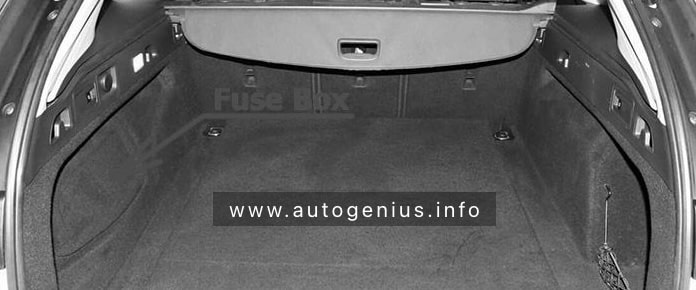
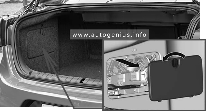
The fuse panel is located on the left side of the boot/cargo area, above the battery.
Sedan: Rotate the catch anticlockwise to unlatch the cover.
Holden Commodore (VF; 2013 – 2017)- fuse box location – luggage compartment (sedan)
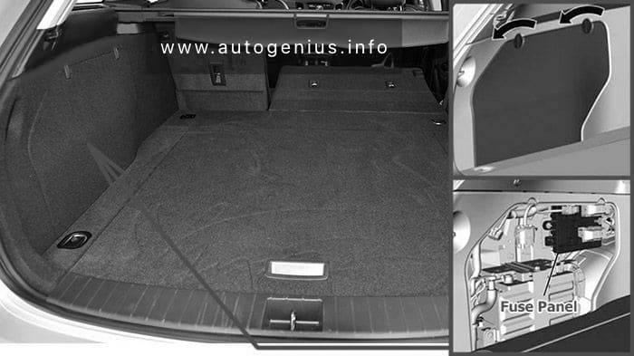
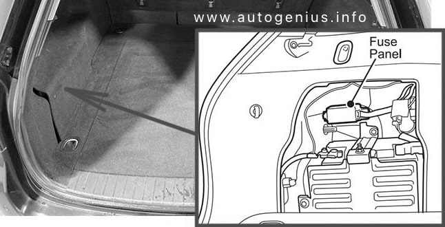
Sportwagon: Remove the battery compartment cover by rotating the latches anticlockwise.
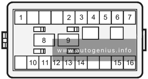
Holden Commodore (VF; 2013 – 2017)- fuse box location – luggage compartment (sportwagon) Fuse Box Diagram
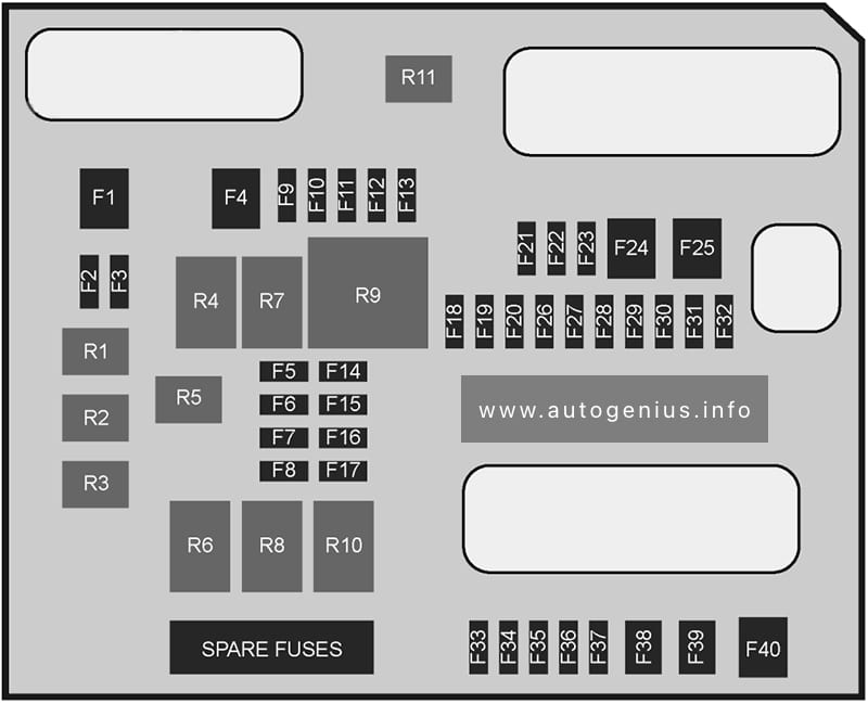
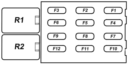
Holden Commodore (VF; 2013 – 2017)- fuse box diagram – luggage compartment
№
Amps
Function
F1
30A
DRIVER FRONT/ LH REAR WINDOW
F2
10A
EMER / VEH / ACCY
F3
15A
TRUNK RELEASE
F4
30A
PASSIVE ENTRY PASSIVE START – BATT 2
F5
15A
RADIO
F6
–
–
F7
–
–
F8
20A
FUEL SYSTEM CONTROL MODULE
F9
30A
MRTD
F10
20A
DECKLID FLASHING LAMPS / EDI MODULE
F11
10A
AUXILIARY BATTERY
F12
–
–
F13
–
–
F14
10A
REAR SEAT ENTERTAINMENT
F15
15A
AUTOMATIC HEADLAMP LEVELLING
F16
–
–
F17
20A
2015-2017: EXHAUST VALVE
F18
10A
ONSTAR
F19
5A
MIRROR / WINDOW MODULE
F20
10A
CANISTER VENT SOLENOID
F21
5A
PASSIVE ENTRY PASSIVE START – BATT 1
F22
10A
MEMORY SEAT MODULE
F23
30A
AMPLIFIER
F24
30A
PASSENGER FRONT / RH REAR WINDOW
F25
30A
ELECTRIC PARK BRAKE
F26
10A
TAILGATE MODULE
F27
10A
CAMERA IGN
F28
15A
FRT VENT SEAT IGN
F29
10A
TRAILER MODULE IGN
F30
15A
ADVANCED PARK ASSIST / SIDE BLIND ZONE ALERT
F31
10A
ENGINE CONTROL MODULE
F32
10A
AUXILIARY GAUGES
F33
10A
RETAINED ACCESSORY POWER
F34
5A
BATTERY VOLTAGE SENSING
F35
30A
TAILGATE MOTOR
F36
20A
REAR ACCESSORY POWER OUTLET
F37
20A
INTERIOR ACCESSORY POWER OUTLET
F38
20A
FRT / LTR
F39
–
–
F40
40A
TRAILER MODULE
Relays
R1
TRUNK RELEASE
R2
ACCESSORY
R3
–
R4
RUN
R5
–
R6
RETAINED ACCESSORY POWER
R7
LOGISTICS MODE
R8
–
R9
–
R10
2015-2017: EXHAUST VALVE
R11
2013-2014: CHILD LOCKS
Note: Relays R1, R2, R3 and R5 are PCB mounted relays.
WARNING: Terminal and harness assignments for individual connectors will vary depending on vehicle equipment level, model, and market.