Holden Astra (AH; 2004 – 2009) – fuse box diagram
Year of production: 2004, 2005, 2006, 2007, 2008, 2009
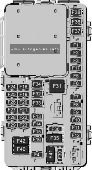
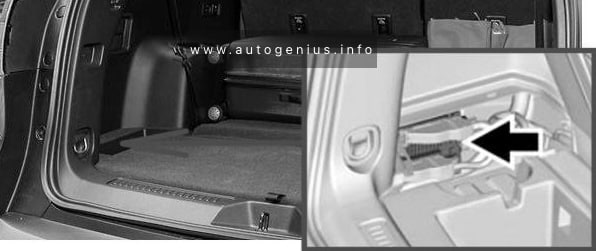
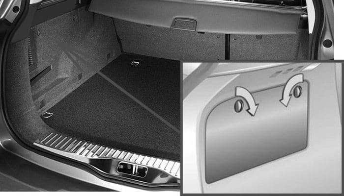
Luggage Compartment Fuse Box
Hatchback and wagon
This fuse box is located behind a cover on the left side of the luggage compartment. Use a coin to turn the locks (illustrated) and fold the cover downward.
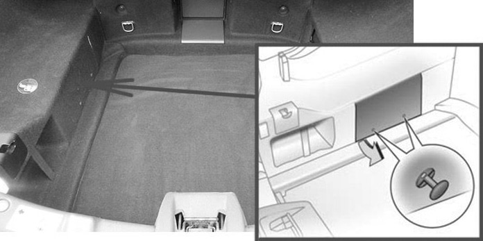
TwinTop
This fuse box is located behind a cover on the left side of the luggage compartment. To open, pull the two knobs, remove the clips and fold the cover upwards.
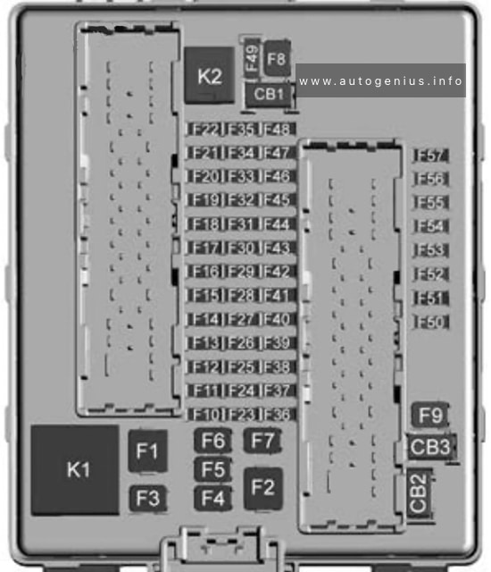
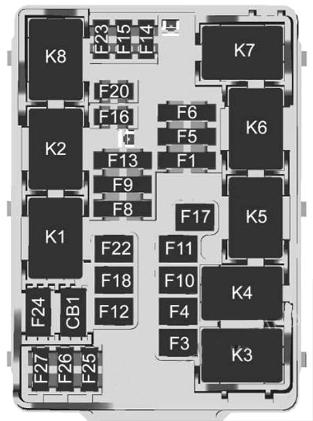
Fuse Box Diagram
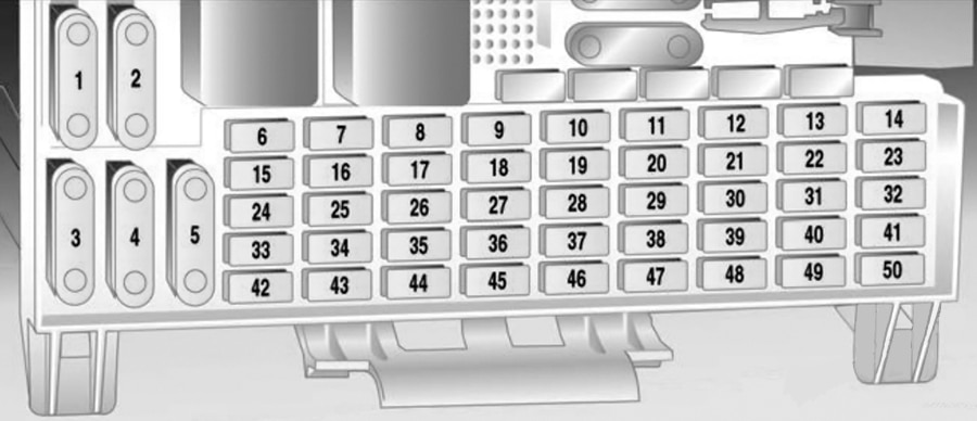
Type 1
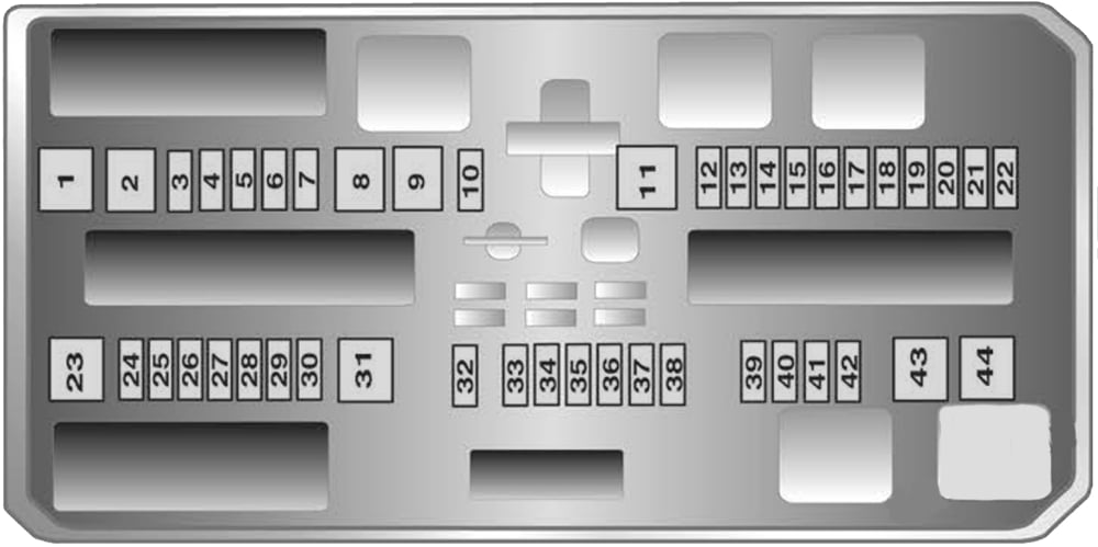
| № | Amps | Description |
|---|---|---|
| 1 | 25A | Electric windows, front |
| 2 | – | – |
| 3 | 7.5A | Instruments |
| 4 | 5A | Heating, air conditioning, climate control system |
| 5 | 7.5A | Airbags |
| 6 | – | – |
| 7 | 7.5A | 2006: Airbags, reverse lamps |
| 8 | – | – |
| 9 | – | – |
| 10 | – | – |
| 11 | 25A | Heated rear window |
| 12 | 15A | Tailgate wiper |
| 13 | 5A | 2006-2009: Parking distance sensor |
| 14 | 7.5A | Heating, air conditioning system |
| 15 | – | – |
| 16 | 5A | 2005: Seat occupancy recognition 2006-2009: Seat occupancy recognition, open start system |
| 17 | 5A | 2006-2009: Rain sensor, air quality sensor, tyre pressure monitoring system, interior mirror |
| 18 | 5A | Instruments, switches |
| 19 | – | – |
| 20 | 10A | 2006-2009: CDC |
| 21 | 7.5A | Heated exterior mirrors |
| 22 | 20A | 2006-2009: Sunroof |
| 23 | 25A | Electric windows, rear |
| 24 | 7.5A | Diagnostics plug |
| 25 | – | – |
| 26 | 7.5A | 2006-2009: Electrically retractable exterior mirrors |
| 27 | – | – |
| 28 | – | – |
| 29 | 15A | 2006-2009: Front accessory socket |
| 30 | 15A | 2006-2009: Rear socket |
| 31 | – | – |
| 32 | – | – |
| 33 | 15A | 2006-2009: Open start system |
| 34 | 25A | 2006-2009: Sun roof, TwinTop |
| 35 | 15A | 2006-2009: Rear socket |
| 36 | 20A | Towing equipment |
| 37 | 5A | 2005: Courtesy lamp |
| 38 | 25A | Central locking system, clamp 30 |
| 39 | 15A | Seat heater, left |
| 40 | 15A | Seat heater, right |
| 41 | – | – |
| 42 | – | – |
| 43 | – | – |
| 44 | – | – |
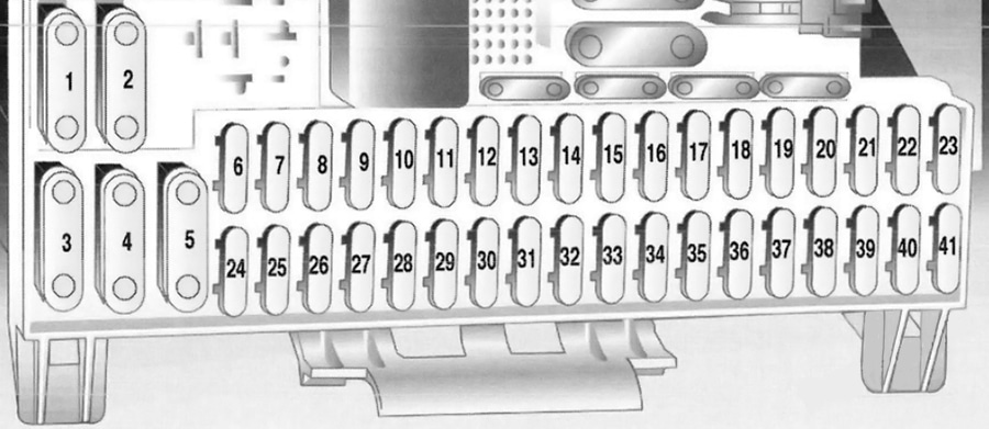
Type 2
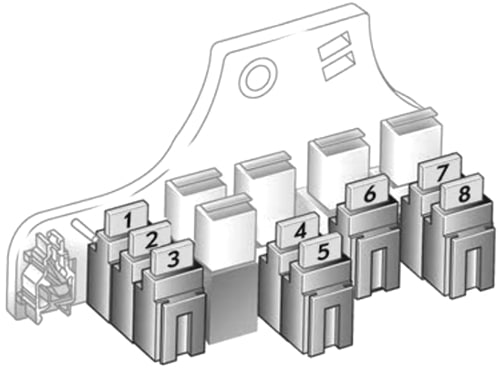
| № | Amps | Description |
|---|---|---|
| 1 | 15A | Fog lamps |
| 2 | – | – |
| 3 | 15A | Luggage compartment accessory socket |
| 4 | 7.5A | Reverse lamps |
| 5 | 30A | Electric windows, rear |
| 6 | 10A | Air conditioning system |
| 7 | 30A | Electric windows, front |
| 8 | 7.5A | Heated exterior mirrors |
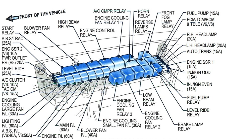
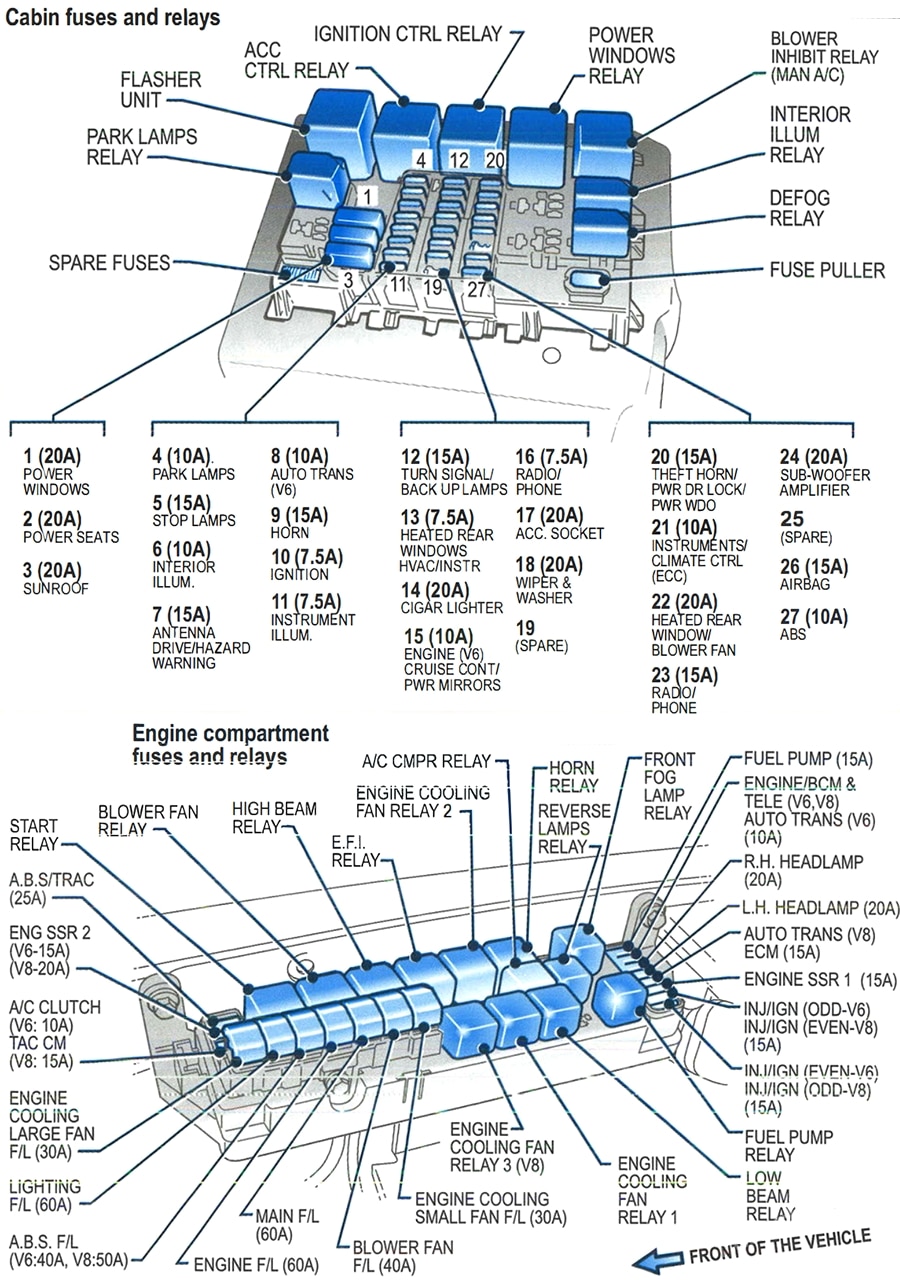
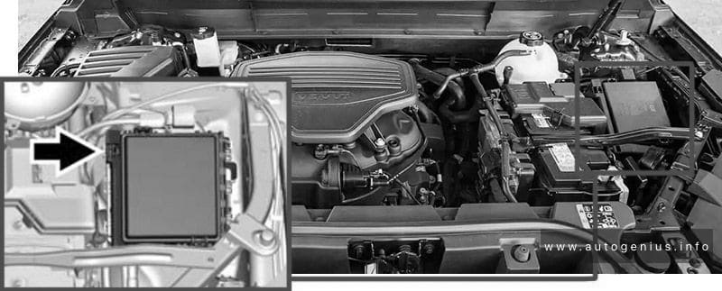
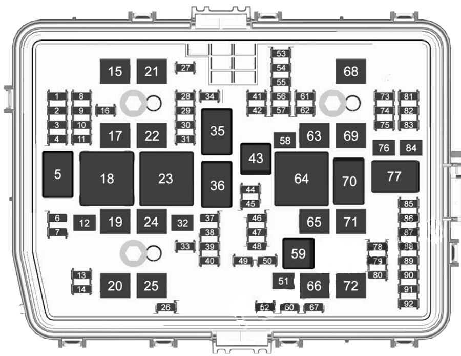
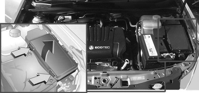
Engine Compartment Fuse Box
Fuse Box Location
This fuse box is located at the front left of the engine compartment.
To open the cover, release the catch by inserting a screwdriver into the opening as far as it will go and swivelling it to the side. Open the cover upwards and remove.
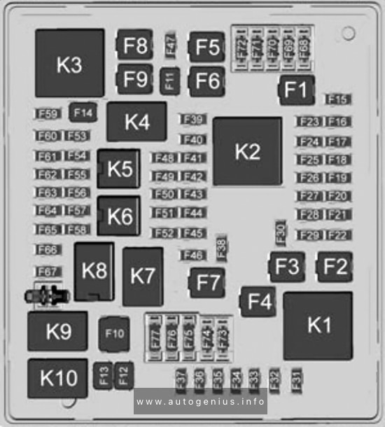
Fuse Box Diagram
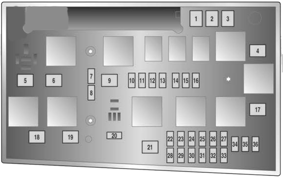
| № | Amps | Description |
|---|---|---|
| 1 | 20A | ABS |
| 2 | 30A | ABS |
| 3 | 30A | Interior fan climate control system |
| 4 | 30A | Interior fan, heating, air conditioning system |
| 5 | 30A/40A | Radiator fan 1 |
| 6 | 20A/30A/40A | Radiator fan 2 |
| 7 | 10A | Windscreen washer system |
| 8 | 15A | Horn |
| 9 | 25A | 2007-2009: Headlamp wash system |
| 10 | – | – |
| 11 | – | – |
| 12 | 5A | 2005-2006: Recirculation pump |
| 13 | 15A | Fog lamps |
| 14 | 30A | Windscreen wipers |
| 15 | 30A | Windscreen wipers |
| 16 | 5A | 2005: Electronic control unit 2006-2009: Electronics Control units, open start system, ABS brake lamp switch, TwinTop |
| 17 | 25A | 2006-2009: Diesel filter heating |
| 18 | 25A | Starter |
| 19 | 15A/30A | Transmission electronics |
| 20 | 10A | Air conditioning system |
| 21 | 20A | Engine electronics |
| 22 | 7.5A | Engine electronics |
| 23 | – | – |
| 24 | 15A | Fuel pump |
| 25 | 15A | Transmission electronics |
| 26 | 10A | Engine electronics |
| 27 | 5A | Power steering |
| 28 | 5A | Transmission electronics |
| 29 | 7.5A | Transmission electronics |
| 30 | 10A | Engine electronics |
| 31 | – | – |
| 32 | 5A | Brake system, air conditioning system, clutch switch |
| 33 | 5A | 2006: Adaptive forward lighting, headlight range adjustment, light switch |
| 34 | 7.5A | Control unit steering column module |
| 35 | 20A | Infotainment system |
| 36 | 7.5A | 2006-2009: Mobile telephone, digital radio, twin audio, display |
| 37 | 20A | Heated front seats |
| 38 | 10A | Brake lights, auto trans information display, cruise control, electronic air conditioning |
| 39 | 5A | Auto trans, engine cooling, air conditioning |
| 40 | 5A | Engine cooling, air cond. |
| 41 | 10A | Heated exterior mirrors |
| 42 | 5A | Courtesy light |
| 43 | – | – |
| 44 | – | – |
| 45 | 5A | Seat heating |
| 46 | 15A | Ignition system |
| 47 | 20A | Stationary heater |
| 48 | 2A | Convertible, folding top |
| 49 | 2A | Convertible, folding top |
| 50 | – | – |
WARNING: Terminal and harness assignments for individual connectors will vary depending on vehicle equipment level, model, and market.