RAM 5500 Chassis Cab (2013 – 2015) – fuse and relay box diagram

RAM 5500 Chassis Cab (2013 – 2015) – fuse and relay box diagram

Year of production: 2013, 2014, 2015


The Ram 5500 Chassis Cab (2013-2015) is a top-tier heavy-duty commercial truck designed for demanding tasks that require maximum power, towing, and payload capabilities. As the largest model in the Ram Chassis Cab lineup, it offers exceptional strength and versatility, making it ideal for various industries such as construction, towing, and custom upfit needs. Built for reliability and durability, the Ram 5500 is well-suited for heavy-duty applications.


Power Distribution Center

Fuse box location

The Power Distribution Center is located in the engine compartment near the battery.
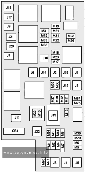
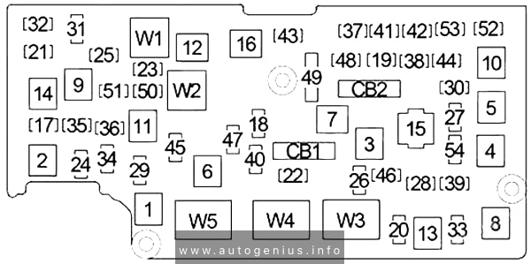
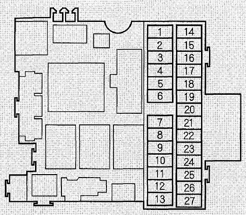
RAM 5500 Chassis Cab - fuse and relay box location - engine compartment
RAM 5500 Chassis Cab – fuse and relay box location – engine compartment


Fuse box diagram

RAM 5500 Chassis Cab - fuse and relay box diagram - engine compartment
RAM 5500 Chassis Cab – fuse and relay box diagram – engine compartment


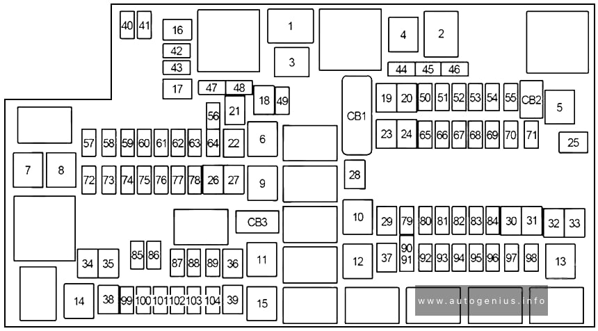
Assignment of the fuses in the engine compartment (2013-2015)

Cavity Cartridge fuse Micro Fuse Description
F01 80 Rad Fan Control Module – If equipped
F03 60 Rad Fan – If Equipped
F05 40 Compressor for Air Suspension – If Equipped
F06 40 Antilock Brakes/Electronic Stability Control Pump
F07 40 Starter Solenoid
F08 30 Emissions Diesel – If Equipped
F09 40 Diesel Fuel Heater – If Equipped
F10 40 Body Controller / Exterior Lighting #2
50 Body Controller / Exterior Lighting #2 – If Equipped with Stop/Start
F11 30 Integrated Trailer Brake Module – If Equipped
F12 40 Body Controller #3 / Interior Lights
F13 40 Blower Motor
F14 40 Body Controller #4 / Power Locks
F15 30 Electric Park Brake Right Side – If Equipped
F19 30 SCR – If Equipped
F20 30 Passenger Door Module
F21 30 Drive Train Control Module
F22 20 Engine Control Module
F23 30 Body Controller #1
F24 30 Driver Door Module
F25 30 Front Wiper Low Speed
30 Front Wiper High Speed
F26 30 Antilock Brakes/Stability Control Module/Valves
F28 20 Trailer Tow Backup Lights – If Equipped
F29 20 Trailer Tow Parking Lights – If Equipped
F30 30 Trailer Tow Receptacle
F32 30 Drive Train Control Module – If Equipped
F33 20 Diesel Fuel Heater #1 – If Equipped /Rear Blower – If Equipped
F34 30 Vehicle System Interface Module #2 – If Equipped
F35 30 Sunroof – If Equipped
F36 30 Rear Defroster– If Equipped
F37 30 Diesel Fuel Heater #2 if equipped
F38 30 Power Inverter 115V AC– If Equipped
F39 30 Vehicle System Interface Module #1– If Equipped
F41 10 Active Grill Shutter
F42 20 Horn
F43 10 Snow Plow (Left) – If Equipped
F44 10 Diagnostic Port
F46 10 Tire Pressure Monitor
F47 10 Snow Plow (Right) – If Equipped
F49 10 Instrument Panel Cluster
F50 20 Air Suspension Control Module – If Equipped
F51 10 Ignition Node Module / Keyless Ignition
F52 5 Battery Sensor
F53 20 Trailer Tow – Left Turn/Stop Lights
F54 20 Adjustable Pedals
F55 20 E38 Radio – If Equipped
F56 15 Additional Diesel Content – If Equipped
F57 20 Transmission
F58 20 (Gas engine) Engine Cooling Pump
25 (Diesel engine)
F60 15 Underhood Lamp
F61 20 Power Take-off Unit – If Equipped
F62 10 Air Conditioning Clutch
F63 20 IgnitionCoils (Gas), Urea Heater (Diesel)
F64 25 Fuel Injectors / Powertrain
F65 10 USB interface
F66 10 Sunroof / Passenger Window Switches /Rain Sensor
F67 10 CD / DVD / Bluetooth Hands-free Module – If Equipped
F69 15 Mod SCR 12V – If Equipped
F70 30 Fuel Pump Motor
F71 25 Amplifier
F72 10 Voltage Stabilizer Modules – If Equipped
F74 20 (Gas engine) Brake Vacuum Pump Gas/Diesel – If Equipped
10 (Diesel engine)
F75 10 Coolant Temperature Valve Actuator
F76 10 Antilock Brakes/Electronic Stability Control
F77 10 Drivetrain Control Module/Front Axle Disconnect Module
F78 10 Engine Control Module / Electric Power Steering
F79 15 Clearance Lights
F80 10 Universal Garage Door Opener / Compass
F81 20 Trailer Tow Right Turn/Stop Lights
F82 10 Steering Column Control Module/ Cruise Control
F84 15 Switch Bank/Instrument Cluster
F85 10 Airbag Module
F86 10 Airbag Module
F87 10 Air Suspension-If Equipped / Trailer Tow / Steering Column Control Module
F88 15 Instrument Panel Cluster
F90 20 Power Outlet (Rear seats) Customer Selectable
F91
F93 20 Cigar Lighter
F94 10 Shifter / Transfer Case Module
F95 10 Rear Camera / Park Assist
F96 10 Rear Seat Heater Switch
F97 25 Rear Heated Seats & Heated Steering Wheel – If Equipped
F98 25 Front Heated Seats – If Equipped
F99 10 Climate Control
F101 15 Electrochromatic Mirror / Smart High Beams – If Equipped
F104 20 Power Outlets (Instrument Panel/Center Console)

WARNING: Terminal and harness assignments for individual connectors will vary depending on vehicle equipment level, model, and market.

RAM 5500 Chassis Cab (2012) – fuse box diagram

RAM 5500 Chassis Cab (2012) – fuse box diagram

Year of production: 2012


The 2012 Ram 5500 Chassis Cab is a heavy-duty truck designed for the most demanding commercial tasks. It sits at the top of Ram’s Chassis Cab lineup, offering impressive power, durability, and versatility for various applications like towing, hauling, and upfitting for custom uses. Built for businesses in industries such as construction, towing, and transportation, the Ram 5500 is designed to handle extreme payloads and heavy-duty towing with ease.


Totally Integrated Power Module (TIPM)

Fuse box location

The totally integrated power module (TIPM) is located in the engine compartment near the battery

RAM 5500 Chassis Cab - fuse and relay box location - engine compartment
RAM 5500 Chassis Cab – fuse and relay box location – engine compartment


Fuse box diagram

RAM 5500 Chassis Cab - fuse and relay box diagram - engine compartment
RAM 5500 Chassis Cab – fuse and relay box diagram – engine compartment


Assignment of the fuses in the engine compartment (2012)

Cavity Cartridge fuse Micro Fuse Description
J01 40 Trailer Tow
J02 30 Electric Brake
J03 30 Diesel Powertrain Control Module – If Equipped
J04 25 Driver Door Node
J05 25 Passenger Door Node
J06 40 Antilock Brakes Pump/Stability Control System
J07 30 Antilock Brakes Valve/Stability Control System
J08 40 Power Seat
J09 30 Sway Bar Module – If Equipped
J10 30 Transfer Case Module
J11 30 Rear Defroster
J12 60 Main Ignition Off Draw (IOD) Fuse
J13 20 Trailer Tow Lamps/Park Lamps
J14 40 Front Blower
J17 40 Starter Motor Solenoid
J18 20 Powertrain Control Module Transmission Range
J19 60 Rad Fan Motor HI/Rad Fan Motor Low
J20 30 Front Wiper Ground/Low/High
J21 20 Washer Control
J22 25 Sunroof Module
M1 15 Stop Switch Lamp
M5 25 115V AC Inverter
M6 20 Power Outlet (Instrument Panel or Front Console)/Rain Snsr
M7 20 Power Outlet (Rear Console or Center Seat)
M8 20 Front Heated Seat & Steering Wheel
M9 20 Rear Heated Seats
M10 15 Hands Free Module/Vanity Lamp/Universal Garage Door Opener Module
M11 10 Climate Control System
M12 30 Radio/Amplifier
M13 20 Main #2 Instrument Cluster/Wireless Control Module/ITM/Siren/Multifunction Switch (Steering Column Module)
M14 20 Back Up Camera (Domestic Only)
M15 20 Power Seat Module(s)/Audio Telematics/Daytime Running Lights Relay/Instrument Cluster/Transfer Case Module
M16 10 Airbag Module
M18 15 Center Stop Lamp
M19 25 Automatic Shutdown 1 and 2
M20 15 Instrument Cluster Interior Lighting /Sw Steering Wheel/Sw Bank
M21 20 Automatic Shutdown 3
M22 10 Horns (Low/High) – Righ
M23 10 Horns (Low/High) – Left
M25 20 Fuel Pump Motor/Diesel Lift Pump – If Equipped
M26 10 Driver’s Door Switch
M27 10 Ignition Switch
M28 15 Powertrain Control Module
M29 10 Tire Pressure Monitor
M30 15 J1962 Diag Connector
M31 20 Back-Up Lamps
M32 10 Airbag Module
M33 10 Powertrain Control Module
M34 10 Park Assist Module/Climate Control System Module/IR Sensor/Compass Module
M35 15 Left Front & Rear Parklamps
M36 20 Power Outlet (Instrument Panel or Center Console)
M37 10 Antilock Brakes/Stability Control System Module/Stoplamp Switch
M38 25 All Door Lock &Unlock

WARNING: Terminal and harness assignments for individual connectors will vary depending on vehicle equipment level, model, and market.

RAM 5500 Chassis Cab (2011) – fuse and relay box diagram

RAM 5500 Chassis Cab (2011) – fuse and relay  box diagram

Year of production: 2011


The Ram 5500 Chassis Cab (2011) is the most heavy-duty truck in the Ram Chassis Cab lineup for that year, offering exceptional towing and payload capacities for demanding commercial applications. It is designed to be upfitted for various roles, including tow trucks, dump trucks, flatbeds, and other specialized commercial uses. The 2011 Ram 5500 is ideal for businesses that require a reliable, durable, and powerful vehicle capable of handling extreme loads and rough work environments.


Totally Integrated Power Module (TIPM)

Fuse box location

The totally integrated power module (TIPM) is located in the engine compartment near the battery

RAM 5500 Chassis Cab  - fuse and relay box location - engine compartment
RAM 5500 Chassis Cab – fuse and relay box location – engine compartment


Fuse box diagram

RAM 5500 Chassis Cab  - fuse and relay box diagram - engine compartment
RAM 5500 Chassis Cab – fuse and relay box diagram – engine compartment


Assignment of the fuses in the engine compartment (2011)

Cavity Cartridge fuse Micro Fuse Description
J01 30 Bat – Presafe #1/CM2200
J02 30 Bat – Trailer Tow Main
J03 25 Bat – Passenger Door Node
J04 40 Bat – ABS Pump
J05 30 Bat – ABS Valve
J06 30 Bat – H/Lamp Wash/MTV/CM2200/Elec Vac Pump
J07 25 Bat – Driver Door Node
J08 30 Bat – DTCM/Axle Locks
J09 30 Bat – Plg/Electric Brake
J10 40 Bat – L/Bar/Off-Road
J11 30 Bat – Sway/Thatchum/Rear Doors
J12 40 Starter Solenoid
J13 60 Bat – Rad Fan #1/#2/SSR
J14 40 Bat – Folding Seat/PZEV
J15 60 Bat – IOD Main
J16 40 Frt HVAC Motor
M17 25 Bat – Sunroof/Skylight
M18 25 TCM/Trans Range
M19 5 Ign R/ACC – Sunroof/Window Sw Illum
M20 25 Frt Wiper
M21 25 Door Locks
M22 20 Fuel Pump
M23 20 Bat – Trlr Light/Pre-Safe #2
M24 20 Bat – Trlr Tow BUX/HGM
M25 10 Bat – J1962 Diag/Mirrors
M26 10 Bat – Ign Sw, WIN, PASS
M27 15 Bat – CHMSL/Brake Sw
M28 10 Bat – Corax TPM/PEM/HVAC Htr Pump
M29 15 Bat – Folding Mirror
M30 25 Bat – Inverter
M31 20 Bat – Pwr Out #1
M32 20 Fr/Rr Washer
M33 15 Bat – NGC/EATX/PCM
M34 15 Bat – CCN/Interior Light/SCM/Sw Bank
M35 20 Ign R-Frt Seat/Vent
M36 20 Ign R-Rear Seat/Steer Wheel
M37 10 Horn #1
M38 20 IOD-CCN/Interior Mods
M39 30 IOD-Amp/Radio
M40 25 Rear Wiper
M41 15 IOD-SDARS/VES2–3/DVD/HFM/UGDO/Vanity Lamp
M42 10 IOD-HVAC, U/Hood Lamp
M43 10 Horn #2
M44 10 IGN R/S-ORC/OCM
M45 10 IGN R-ORC/Trail Tow (BUX) Sense
M46 20 IGN R-Trail Tow (BUX)
M47 10 IGN R-H/Lamp Wash/HVAC/Park Assist/Ir Sns
M48 20 IGN R/ACC-Pwr Outlet #2
M49 20 IGN R/ACC/Bat-Pwr Outlet #3
M50 25 ASD #1, #2
M51 20 ASD #3
M52 10 IGN R/S-SWAY/TCASE/DTCM/FAD
M53 15 IGN R/S-MFSW/CNN/SCM/TPM/RR View
M54 20 IOD – Spare

WARNING: Terminal and harness assignments for individual connectors will vary depending on vehicle equipment level, model, and market.

RAM 5500 Chassis Cab (2010) – fuse box diagram

RAM 5500 Chassis Cab (2010) – fuse box diagram

Year of production: 2010

Totally Integrated Power Module (TIPM)

The totally integrated power module (TIPM) is located in the engine compartment near the battery

Cavity Cartridge fuse Micro Fuse Description
J01 30 Bat – Presafe #1
J02 30 Bat – Trailer Tow Main
J03 25 Bat – Passenger Door Node
J04 40 Bat – ABS Pump
J05 30 Bat – ABS Valve
J06 30 Bat – H/Lamp Wash/MTV/CM2200/Elec Vac Pump
J07 25 Bat – Driver Door Node
J08 30 Bat – DTCM/Axle Locks
J09 30 Bat – Plg/Electric Brake
J10 40 Bat – L/Bar/Off-Road
J11 30 Bat – Sway/Thatchum/Rear Doors
J12 40 Starter Solenoid
J13 60 Bat – Rad Fan #1/#2/SSR
J14 40 Bat – Folding Seat/PZEV
J15 60 Bat – IOD Main
J16 40 Frt HVAC Motor
M17 25 Bat – Sunroof/Skylight
M18 25 TCM/Trans Range
M19 5 Ign R/ACC – Sunroof/Window Sw Illum
M20 25 Frt Wiper
M21 25 Door Locks
M22 20 Fuel Pump
M23 20 Bat – Trlr Light/Pre-Safe #2
M24 20 Bat – Trlr Tow BUX/HGM
M25 10 Bat – J1962 Diag/Mirrors
M26 10 Bat – Ign Sw, WIN, PASS
M27 15 Bat – CHMSL/Brake Sw
M28 10 Bat – Corax TPM/PEM/HVAC Htr Pump
M29 15 Bat – Folding Mirror
M30 25 Bat – Inverter
M31 20 Bat – Pwr Out #1
M32 20 Fr/Rr Washer
M33 15 Bat – NGC/EATX/PCM
M34 15 Bat – CCN/Interior Light/SCM/Sw Bank
M35 20 Ign R-Frt Seat/Vent
M36 20 Ign R-Rear Seat/Steer Wheel
M37 10 Horn #1
M38 20 IOD-CCN/Interior Mods
M39 30 IOD-Amp/Radio
M40 25 Rear Wiper
M41 15 IOD-SDARS/VES2–3/DVD/HFM/UGDO/Vanity Lamp
M42 10 IOD-HVAC, U/Hood Lamp
M43 10 Horn #2
M44 10 IGN R/S-ORC/OCM
M45 10 IGN R-ORC/Trail Tow (BUX) Sense
M46 20 IGN R-Trail Tow (BUX)
M47 10 IGN R-H/Lamp Wash/HVAC/Park Assist/Ir Sns
M48 20 IGN R/ACC-Pwr Outlet #2
M49 20 IGN R/ACC/Bat-Pwr Outlet #3
M50 25 ASD #1, #2
M51 20 ASD #3
M52 10 IGN R/S-SWAY/TCASE/DTCM/FAD
M53 15 IGN R/S-MFSW/CNN/SCM/TPM/RR View
M54 20 IOD – Spare
F91

WARNING: Terminal and harness assignments for individual connectors will vary depending on vehicle equipment level, model, and market.

Honda S2000 (2008 – 2009) – fuse box diagram

Honda S2000 (2008 – 2009) – fuse box diagram

Year of production: 2008, 2009

Interior fuse box

Honda S2000 – fuse box –
interior
Number Ampere rating [A] Circuit protected
1 7,5 Windshield Wiper, Auto Stop Signal
2 15 Washer Motor
3 7,5 IGP (DBW)
4 7,5 IGP (LAF)
5 10 Accessory Socket
6 20 Windshield Wiper
7 7,5 Tum signal  Light
8 15 ACG
9 7,5 Meter, Backup Lights
10 Not Used
11 7,5 Engine Start
12 15 Fuel Pump, SRS
13 10 SRS
14 10 Daytime Running Lights
15 10 Keyless Entry
16 7,5 Backup
17 7,5 Interior Light
18 10 Small Lights
19 15 Radio*
20 7,5 TPMS
21 7,5 Heater Control, Cooling Fan Relay
22 7,5 Power Mirrors
23 20 Right Power Window
24 20 Left Power Window
25 15 IG Coil
26 20 LAF
27 15 DBW
*: if equipped

Engine compartment fuse box (main fuse box)

Honda S2000 – fuse box –
engine compartment (main box)
Number Ampere rating [A] Circuit protected
1 Lighting 1 Relay
2 Lighting 2 Relay
3 Horn Relay
4 40 Power Window Motor
5 20 Right Roof Motor*1
6 20 Accessory Socket
7 30 BackUp ACC
8 20 Left Soft TopMotor*1
9 40 Heater Motor
10 20 Condenser Fan*2
11 20 DBW
12 Condenser Fan Relay*2
13 Cooling Fan Relay
14 Magnetic Clutch Relay*2
15 20 Right Headlight
16 15 ACGS
17 10 Hazard Warning Lights
18 20 Cooling Fan
19 Not used
20 10 Stop
21 20 Left Headlight
22 20 VSA F/S
23 30 VSA Motor
24 100 Battery
25 40 IGl Main
*1 : Except CR models
*2 : if equipped

Engine compartment fuse box (auxiliary fuse box)

Honda S2000 – fuse box –
engine compartment (auxiliary box)
Number Circuit protected Ampere rating [A]
1 20 Rear Window Defogger
2 Not used
3 70 EPS
4 Not used

WARNING: Terminal and harness assignments for individual connectors will vary depending on vehicle equipment level, model, and market.

Honda S2000 (2006 – 2007) – fuse box diagram

Honda S2000 (2006 – 2007) – fuse box diagram

Year of production: 2006, 2007

Interior fuse box

Honda S2000 – fuse box –
interior
Number Ampere rating [A] Circuit protected
1 7,5 Windshield Wiper, Auto Stop Signal
2 15 Washer Motor
3 7,5 IGP (DBW)
4 7,5 IGP (LAF)
5 10 Accessory Socket
6 20 Windshield Wiper
7 7,5 Tum signal  Light
8 15 ACG
9 7,5 Meter, Backup Lights
10 Not Used
11 7,5 Engine Start
12 15 Fuel Pump, SRS
13 10 SRS
14 10 Daytime Running Lights
15 10 Keyless Entry
16 7,5 Backup
17 7,5 Interior Light
18 10 Small Lights
19 15 Radio
20
21 7,5 Heater Control, Cooling Fan Relay
22 7,5 Power Mirrors
23 20 Right Power Window
24 20 Left Power Window
25 15 IG Coil
26 20 LAF
27 15 DBW

Engine compartment fuse box (main fuse box)

Honda S2000 – fuse box –
engine compartment (main box)
Number Ampere rating [A] Circuit protected
1 Lighting 1 Relay
2 Lighting 2 Relay
3 Horn Relay
4 40 Power Window Motor
5 20 Right Roof Motor
6 Not used
7 30 BackUp ACC
8 20 Left Roof Motor
9 40 Heater Motor
10 20 Condenser Fan
11 20 DBW
12 Condenser Fan Relay
13 Cooling Fan Relay
14 Magnetic Clutch Relay
15 20 Right Headlight
16 15 ACGS
17 10 Hazard Warning Lights
18 20 Cooling Fan
19 Not used
20 10 Stop
21 20 Left Headlight
22 20 VSA F/S
23 30 VSA Motor
24 100 Battery
25 40 IGl Main

Engine compartment fuse box (auxiliary fuse box)

Honda S2000 – fuse box –
engine compartment (auxiliary box)
Number Circuit protected Ampere rating [A]
1 20 Rear Window Defogger
2 Not used
3 70 EPS
4 Not used

WARNING: Terminal and harness assignments for individual connectors will vary depending on vehicle equipment level, model, and market.

Honda S2000 (2002 – 2005) – fuse box diagram

Honda S2000 (2002 – 2005) – fuse box diagram

Year of production: 2002, 2003, 2004, 2005

Interior fuse box

Honda S2000 – fuse box –
interior
Number Ampere rating [A] Circuit protected
1 7,5 Windshield Wiper, Auto Stop Signal
2 15 Washer Motor
3 Not used
4 Not used
5 10 Accessory Socket
6 20 Windshield Wiper
7 7,5 Tum signal  Light
8 15 ACG
9 7,5 Instrument Light, Back·up Lights
10 15 Ignition Coil
11 7,5 Engine Start
12 15 Fuel Pump, SRS
13 10 SRS
14 10 Daytime Running Lights*
15 10 Keyless Entry
16 7,5 Back-up
17 7,5 Interior Light
18 10 Small Lights
19 15 Radio
20 7,5 Starter Signal
21 7,5 Heater Control, Cooling Fan Relay
22 7,5 Power Mirrors
23 20 Right Power Window
24 20 Left Power Window
25 Not used
26 Not used
27 Not used
*: Canadian Model

Engine compartment fuse box (main fuse box)

Honda S2000 – fuse box –
engine compartment (main box)
Number Ampere rating [A] Circuit protected
1 Lighting 1 Relay
2 Lighting 2 Relay
3 Horn Relay
4 40 Power Window Motor
5 20 Right Roof Motor
6 Not used
7 30 BackUpACC
8 20 Left Roof Motor
9 40 Heater Motor
10 20 Condenser Fan
11 Not used
12 Condenser Fan Relay
13 Cooling Fan Relay
14 Magnetic Clutch Relay
15 20 Right Headlight
16 15 ACGS
17 10 Hazard Warning Lights
18 20 Cooling Fan
19 Not used
20 10 Stop
21 20 Left Headlight
22 20 ABS F/S
23 30 ABS Motor
24 100 Battery
25 40 IGl Main

Engine compartment fuse box (auxiliary fuse box)

Honda S2000 – fuse box –
engine compartment (auxiliary box)
Number Circuit protected Ampere rating [A]
1 20 Rear Window Defogger
2 Not used
3 Not used
4 70 EPS
5 60 Air Pump

WARNING: Terminal and harness assignments for individual connectors will vary depending on vehicle equipment level, model, and market.

Honda S2000 (2001) – fuse box diagram

Honda S2000 (2001) – fuse box diagram

Year of production: 2001

Interior fuse box

Honda S2000 – fuse box –
interior
Number Ampere rating [A] Circuit protected
1 7,5 Windshield Wiper, Auto Stop Signal
2 15 Washer Motor
3 Not used
4 Not used
5 10 Accessory Socket
6 20 Windshield Wiper
7 7,5 Tum signa;  Light
8 15 ACG
9 7,5 Instrument Light, Back·up Lights
10 15 Ignition Coil
11 7,5 Engine Start
12 15 Fuel Pump, SRS
13 10 SRS
14 10 Daytime Running Lights*
15 10 Keyless Entry
16 7,5 Back-up
17 7,5 Interior Light
18 10 Small Lights
19 15 Radio
20 7,5 Starter Signal
21 7,5 Heater Control, Cooling Fan Relay
22 7,5 Power Mirrors
23 20 Right Power Window
24 20 Left Power Window
25 Not used
26 Not used
27 Not used
*: Canadian Model

Engine compartment fuse box (main fuse box)

Honda S2000 – fuse box –
engine compartment (main box)
Number Circuit protected Ampere rating [A]
1 Lighting 1 Relay
2 Lighting 2 Relay
3 Horn Relay
4 40 Power Window Motor
5 20 Right Roof Motor
6 Not used
7 30 BackUpACC
8 20 Left Roof Motor
9 40 Heater Motor
10 20 Condenser Fan
11 Not used
12 Condenser Fan Relay
13 Cooling Fan Relay
14 Magnetic Clutch Relay
15 20 Right Headlight
16 15 ACGS
17 10 Hazard Warning Lights
18 20 Cooling Fan
19 Not used
20 10 Stop
21 20 Left Headlight
22 20 ABS F/S
23 30 ABS Motor
24 100 Battery
25 40 IGl Main

Engine compartment fuse box (auxiliary fuse box)

Honda S2000 – fuse box –
engine compartment (auxiliary box)
Number Circuit protected Ampere rating [A]
1 Not used
2 Not used
3 Not used
4 70 EPS
5 60 Air Pump

WARNING: Terminal and harness assignments for individual connectors will vary depending on vehicle equipment level, model, and market.

Honda S2000 (2000) – fuse box diagram

Honda S2000 (2000) – fuse box diagram

Year of production: 2000

Interior fuse box

Honda S2000 – fuse box –
interior
Number Ampere rating [A] Circuit protected
1 7,5 Windshield Wiper, Auto Stop Signal
2 15 Washer Motor
3 Not used
4 Not used
5 10 Accessory Socket
6 20 Windshield Wiper
7 7,5 Tum Light
8 15 ACG
9 7,5 Instrument Light, Back·up Lights
10 15 Ignition Coil
11 7,5 Engine Start
12 15 Fuel Pump, SRS
13 10 SRS
14 10 Daytime Running Lights*
15 10 Keyless Entry
16 7,5 Back-up
17 7,5 Interior Light
18 10 Small Lights
19 15 Radio
20 7,5 Starter Signal
21 7,5 Heater Control, Cooling Fan Relay
22 7,5 Power Mirrors
23 20 Right Power Window
24 20 Left Power Window
25 Not used
26 Not used
27 Not used
*: Canadian Model

Engine compartment fuse box (main fuse box)

Honda S2000 – fuse box –
engine compartment (main box)
Number Circuit protected Ampere rating [A]
1 Lighting 1 Relay
2 Lighting 2 Relay
3 Horn Relay
4 40 Power Window Motor
5 20 Right Roof Motor
6 Not used
7 30 BackUpACC
8 20 Left Roof Motor
9 40 Heater Motor
10 20 Condenser Fan
11 Not used
12 Condenser Fan Relay
13 Cooling Fan Relay
14 Magnetic Clutch Relay
15 20 Right Headlight
16 15 ACGS
17 10 Hazard Warning Lights
18 20 Cooling Fan
19 Not used
20 10 Stop
21 20 Left Headlight
22 20 ABS F/S
23 30 ABS Motor
24 100 Battery
25 40 IGl Main

Engine compartment fuse box (auxiliary fuse box)

Honda S2000 – fuse box –
engine compartment (auxiliary box)
Number Circuit protected Ampere rating [A]
1 Not used
2 Not used
3 Not used
4 70 EPS
5 60 Air Pump

WARNING: Terminal and harness assignments for individual connectors will vary depending on vehicle equipment level, model, and market.

Honda Ridgeline (from 2017) – fuse box diagram

Honda Ridgeline (from 2017) – fuse box diagram

Year of production: 2017

Engine compartment fuse box type A

Number Circuit protected Ampere rating [A]
1 70*1
AC INVERTER 70*2
RR BLOWER 30*1
30*2
VSA MTR 40
VSA FSR 20
MAIN FAN 30*1
30*2
MAIN FUSE 150
2 SUB FAN 30
WIP MTR 30
WASHER 20
(20)
(30)
FR BLOWER 40
AUDIO AMP (30)
RR DEF 30*1
30*2
(40)
30*1
RR DEF 30*2
(20)
3 –*1
RR BLOWER 30*2
–*1
30*2
–*1
30*2
–*1
MAIN FAN 30*2
4 SMALL 10*1
STOP 10*2
5
6 STOP 10*1
SMALL 10*2
7
8 L H/L LO 10*1
IGPS 7,5*2
9
10 R H/L LO 10*1
L H/L LO 10*2
11 IGPS 7,5*1
R H/L LO 10*2
12 INJECTOR 20*1
IG COIL 15*2
13 H/L LO MAIN 20*1
DBW 15*2
14 USB (15)
15 FR FOG (15)*1
BACK UP 10*2
16 HAZARD 15*1
MAIN RLY 15*2
17 AS P/SEAT (REC) (20)
18 AS P/SEAT (SLI) (20)
19 ACM 20
20 MG CLUTCH 7,5
21 MAIN RLY 15*1
HAZARD 15*2
22 FI SUB 15
23 IG COIL 15*1
INJECTOR 20*2
24 DBW 15*1
H/L LO MAIN 20*2
25 SMALL/STOP MAIN 20
26 BACK UP 10*1
FR FOG 15*2
27 H/STEERING WHEEL (10)
28 HORN 10
29 RADIO 20
*1: Models without the AC power outlet
*2: Models with the AC power outlet

Engine compartment fuse box yype B

Number Circuit protected Ampere rating [A]
1 ST CUT1 40
4WD (20)
IG MAIN 30
IG MAIN2 30
F/B MAIN2 60
F/B MAIN 60
EPS 60
2
3 TRL E-BRAKE (20)
4 BMS 7,5
5 H/L HI MAIN 20
6 +B TRL HAZARD (7,,5)
7 +B TRL BACKUP (7,5)
8 CTR ACC SOCKET 20
9 TRAILER SMALL (20)
10 ACC/IG2_MAIN 10
11 TRL CHARGE (20)
12
13
14
15 FR DE-ICER (15)
16 RR _HTD SEAT (20)
17 STRLD 7,5

Interior fuse box

Honda Ridgeline – fuse box – interior
Number Circuit protected Ampere rating [A]
1 DR P/W 20
2 DOOR LOCK 20
3 SMART 7,5
4 AS P/W 20
5 FR ACC SOCKET 20
6 FUEL PUMP 20
7 ACG 15
8 FRONT WIPER 7,5
9 ABS/VSA 7,5
10 SRS 10
11 REAR LEFT P/W 20
12 BACK P/W (20)
13 REAR RIGHT P/W 20
14 S/R FUEL LID 20
15 DR P/SEAT (REC) (20)
16 CARGO LT 7,5
17 FR SEAT HEATER (20)
18 INTR LT 7,5
19 DR REAR DOOR UNLOCK 10
20 AS SIDE DOOR UNLOCK 10
21 DRL 7,5
22 KEY LOCK 7,5
23 A/C 7,5
24 IG1a FEED BACK 7,5
25 INST PANEL LIGHTS 7,5
26 LUMBAR SUPPORT (7,5)
27 PARKING LIGHTS 7,5
28 OPTION 10
29 METER 7,5
30
31 MISS SOL 7,5
32 SRS 7,5
33 AS SIDE DOOR LOCK 10
34 DR DOOR LOCK 10
35 DR DOOR UNLOCK 10
36 DR P/SEAT (SLIDE) (20)
37 RIGHT H/L HI 10
38 LEFT H/L HI 10
39 IG1b FEED BACK 7,5
40 ACC 7,5
41 DR REAR DOOR LOCK 10
42
*: If equipped

Interior fuse box upper area (driver’s side)

Honda Ridgeline – fuse box – interior (upper area)
Number Ampere rating [A] Circuit protected
1 7,5 STS

WARNING: Terminal and harness assignments for individual connectors will vary depending on vehicle equipment level, model, and market.