Buick LaCrosse (2017) – fuse box diagram
Year of production: 2017
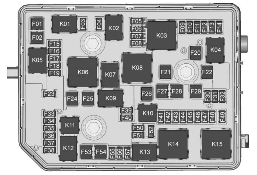
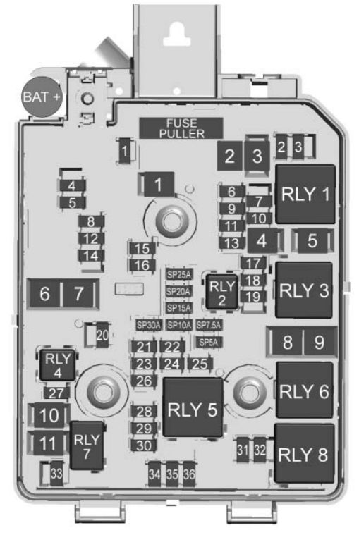
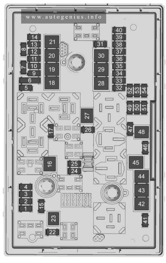
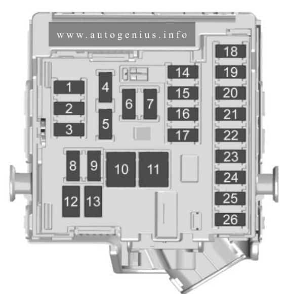
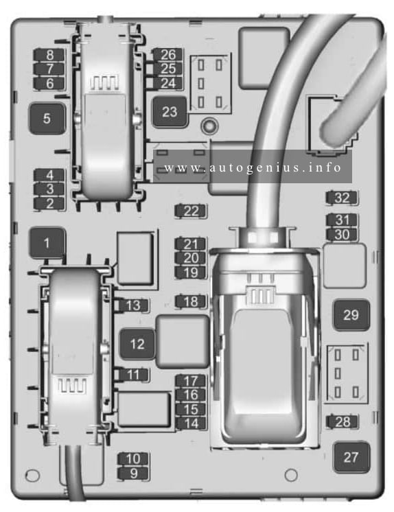
Engine Compartment Fuse Block
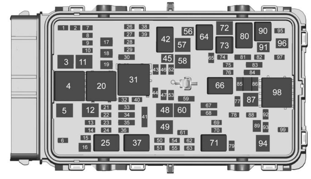
| Fuses | Usage |
| 1 | — |
| 2 | — |
| 3 | ABS pump |
| 5 | AC DC inverter |
| 6 | Rear closure |
| 7 | Left corner lamp |
| 8 | Power windows/ Rearview mirror/ Power seats |
| 9 | Engine boost |
| 10 | Semi-active damping system |
| 11 | DC DC Battery 1 |
| 12 | Rear window defogger |
| 13 | Heated mirrors |
| 14 | — |
| 15 | Passive entry/ Passive start |
| 16 | Front wipers |
| 17 | Passenger power seat |
| 18 | ABS valve |
| 19 | Driver power sea |
| 21 | Sunroof |
| 22 | Right corner lamp |
| 23 | Auto headlamp leveling |
| 24 | — |
| 26 | Transmission control module/Ignition |
| 27 | Instrument panel/ Ignition |
| 28 | Electronic precision shift/Ignition |
| 29 | Rear vision camera/ Ventilation |
| 30 | Malfunction indicator lamp/Shift solenoid |
| 32 | Canister vent solenoid |
| 33 | Front heated seats |
| 34 | Rear heated seat/ Vehicle body safety module/Energy storage system fan |
| 35 | Fog lamps |
| 36 | Fuel module |
| 38 | — |
| 39 | — |
| 40 | Steering columnn lock |
| 41 | — |
| 43 | Heated steering wheel |
| 44 | Headlamp leveling/ Rear seat ventilation |
| 45 | — |
| 46 | Engine control module/Ignition |
| 47 | — |
| 48 | Engine boost/Left cooling fan |
| 49 | DC DC battery 2/AWD |
| 50 | — |
| 51 | — |
| 52 | — |
| 53 | — |
| 54 | — |
| 55 | — |
| 56 | — |
| 57 | Transmission auxiliary pump |
| 58 | TRCM |
| 59 | High-beam headlamps |
| 60 | Cooling fan |
| 61 | — |
| 62 | — |
| 63 | — |
| 65 | A/C HEV |
| 67 | — |
| 68 | — |
| 69 | Right HID low-beam headlamps |
| 70 | Left HID low-beam headlamps |
| 72 | Starter pinion |
| 74 | Starter motor |
| 75 | Engine control module |
| 76 | Powertrain – off engine |
| 77 | — |
| 78 | Horn |
| 79 | Washer pump |
| 81 | Transmission control module/ Engine control module |
| 82 | — |
| 83 | Ignition coils |
| 84 | Powertrain – on engine |
| 85 | Engine control module switch 2 |
| 86 | Engine control module switch 1 |
| 87 | SAI reaction pump |
| 88 | Aeroshutter |
| 89 | Headlamp washer |
| 91 | — |
| 91 | TPIM motor generator unit pump |
| 95 | Headlamp leveling |
| 96 | Fuel heater |
| 97 | — |
| 99 | Coolant pump |
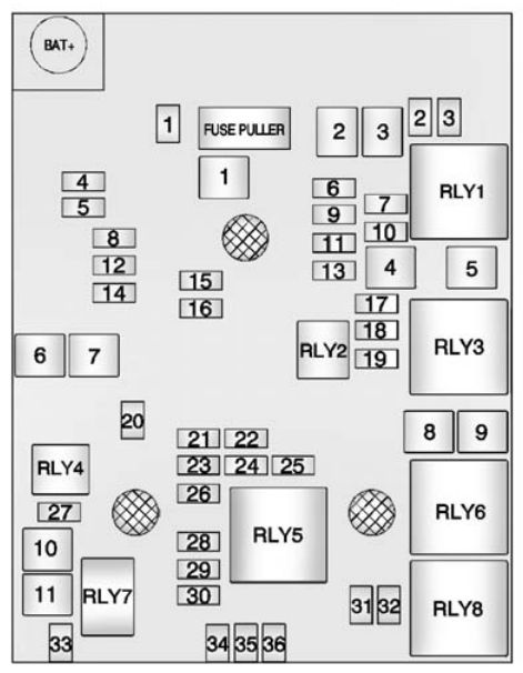
| Relays | Usage |
| 4 | AC DC inverter |
| 20 | Rear defogger |
| 25 | Front wiper control |
| 31 | Run/Crank |
| 37 | Front wiper speed |
| 42 | Transmission auxiliary pump |
| 64 | A/C control |
| 66 | Powertrain |
| 71 | HID low-beam headlamps |
| 73 | Starter motor |
| 80 | Starter pinion |
| 90 | SAI reaction solenoid |
| 94 | Headlamp washer |
| 98 | SAI reaction pump |
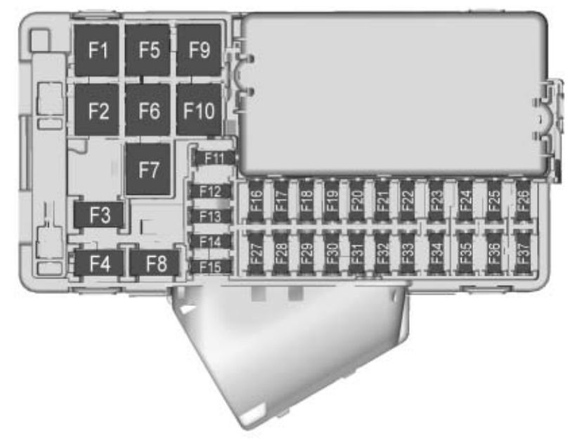
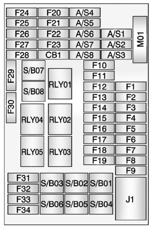
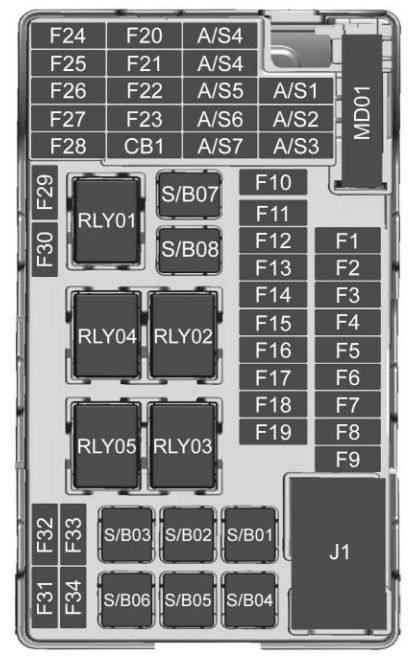
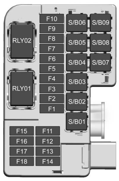
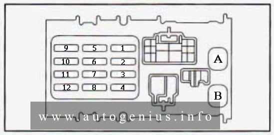
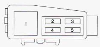
Instrument Panel Fuse Block
The instrument panel fuse block is in the instrument panel, on the driver side of the vehicle.
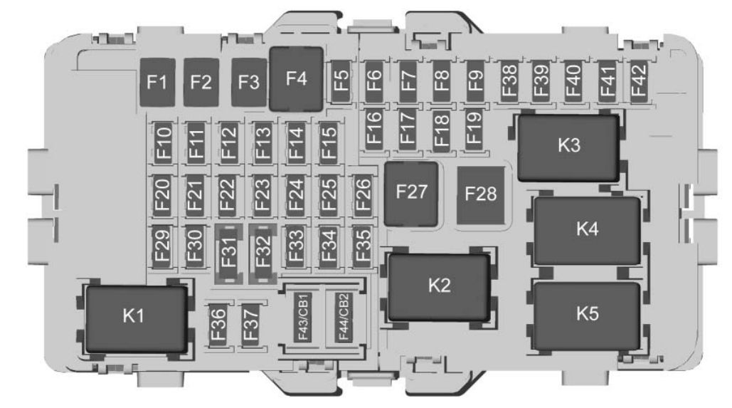
| Fuses | Usage |
| F1 | Left window |
| F2 | Right window |
| F3 | — |
| F4 | HVAC blower |
| F5 | Battery 2 |
| F6 | Electric steering column |
| F7 | — |
| F8 | Battery 3 |
| F9 | Engine control module/Battery |
| F10 | Body control module 2 On/Off |
| F11 | — |
| F12 | — |
| F13 | — |
| F14 | — |
| F15 | Transmission control module On/Off |
| F16 | Amplifier |
| F17 | — |
| F18 | Battery 7 |
| F19 | — |
| F20 | Battery 1 |
| F21 | Battery 4 |
| F22 | Battery 6 |
| F23 | Electric steering column lock |
| F24 | Sensing and diagnostic module |
| F25 | Diagnostic link |
| F26 | — |
| F27 | AC DC inverter |
| F28 | — |
| F29 | Body control module 8 |
| F30 | Overhead console |
| F31 | Steering wheel control |
| F32 | — |
| F33 | HVAC |
| F34 | Center gateway module |
| F35 | Integrated chassis control module |
| F36 | Charger |
| F37 | Auxiliary power outlet/Cigar lighter |
| F38 | OnStar |
| F39 | Monitor |
| F40 | Object detection |
| F41 | Body control module 1 On/Off |
| F42 | Radio |
| F43 | Circuit breaker 1 |
| F44 | Circuit breaker 2 |
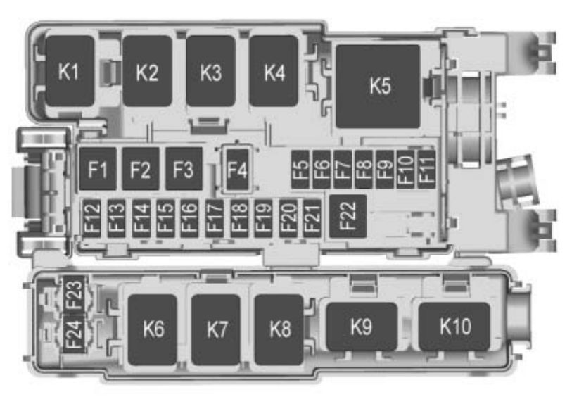
| K1 | — |
| K2 | Retained accessory power |
| K3 | — |
| K4 | — |
| K5 | Logistics |
WARNING: Terminal and harness assignments for individual connectors will vary depending on vehicle equipment level, model, and market.