Jeep Cherokee XJ (1997 – 2001) – fuse box diagram
Year of production: 1997, 1998, 1999, 2000, 2001
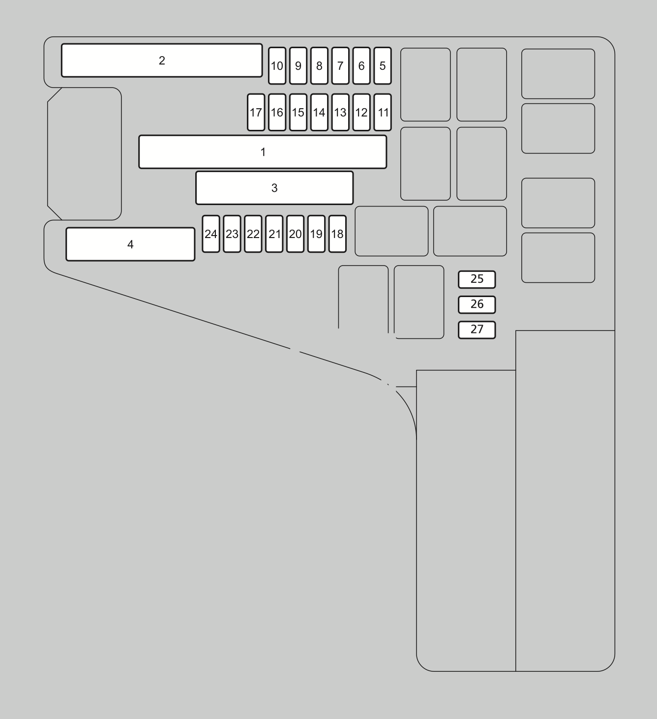
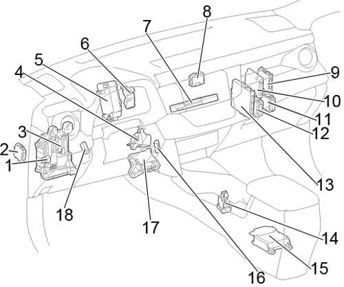
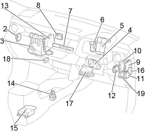
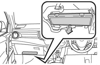
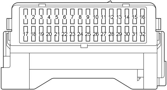
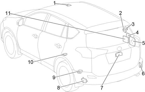
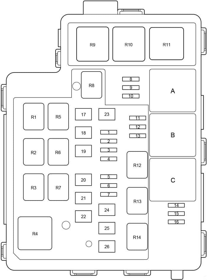
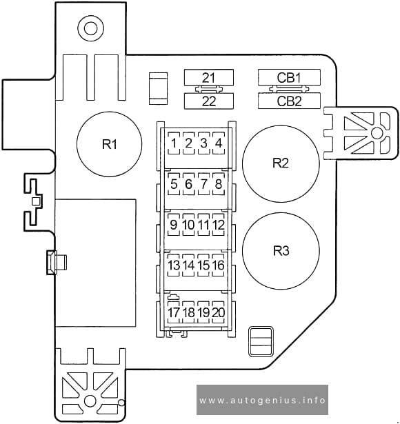
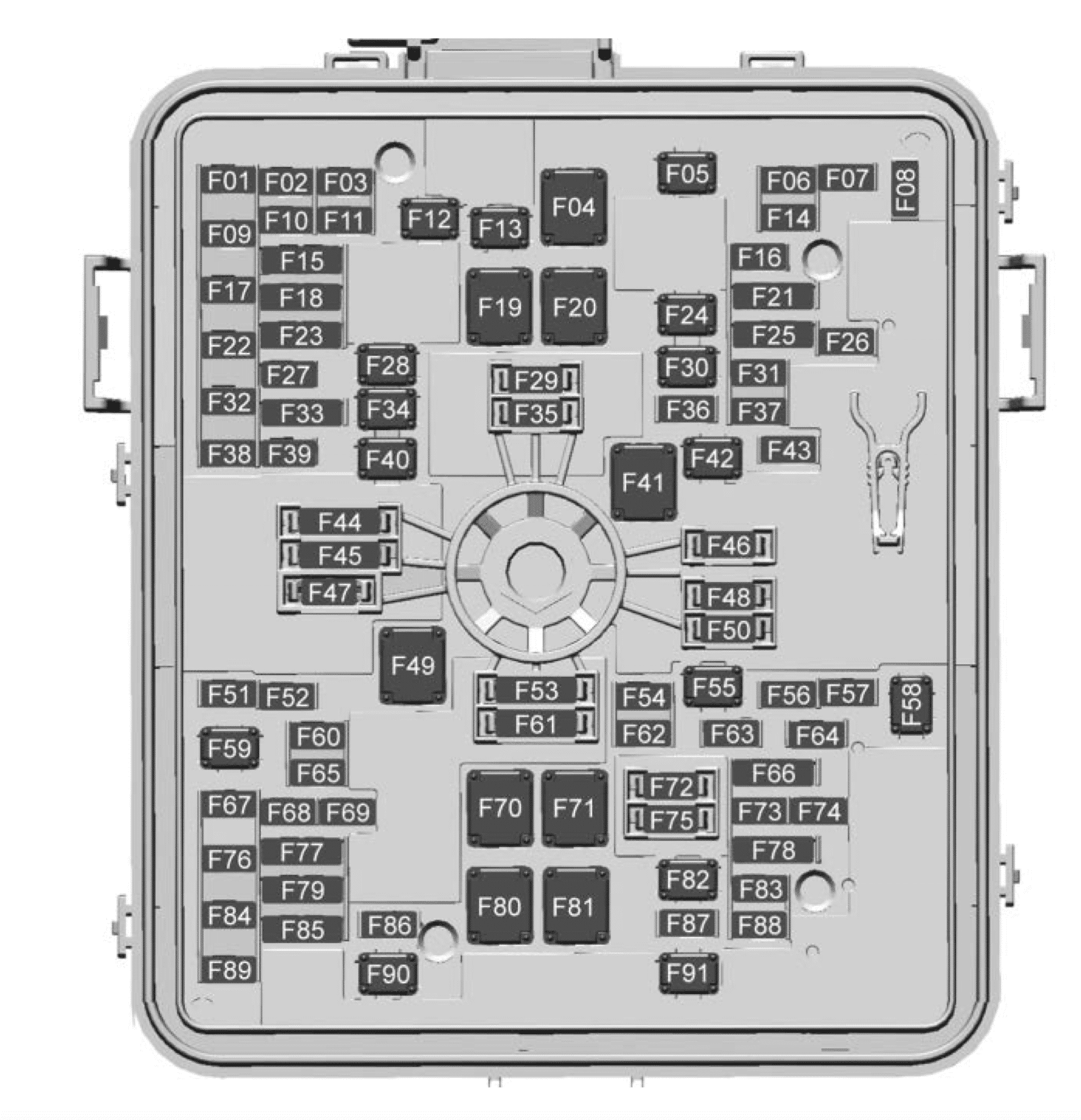
Passenger Compartment Fuse Box
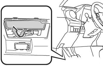
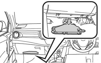
It is located behind the lid under the glove compartment.
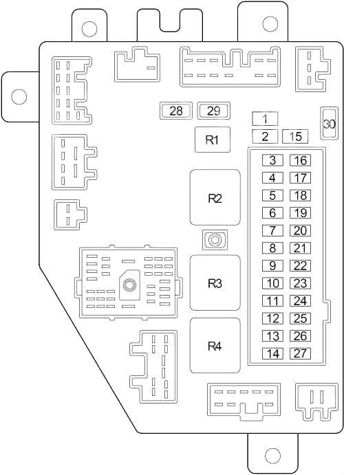
| No. |
A |
Circuit Protected |
| 1 | 25 | Power Outlet |
| 2 | 25 | Cigar Lighter |
| 3 | 10 | Left Headlamp (High Beam), Fog Lamp Relay No.1 |
| 4 | 10 | Left Headlamp (Low Beam), Leveling Motor |
| 5 | 10 | Right Headlamp (Low Beam), Leveling Motor, Headlamp Leveling Switch, Daytime Running Lamp Module |
| 6 | 5 | Instrument Cluster, Radio, Rear Wiper/Washer Switch, A/C Heater Control or Heater Control, Rear Window Defogger Switch, Extended Idle Switch, Front Fog Lamp Switch, Rear Fog Lamp Switch, Transmission Range Indicator Illumination (PRNDL), Transfer Case Switch Illumination |
| 7 | 10 | Left Tail Lamp, Left Front Park Lamp, Left Side Marker Lamp, Trailer Tow Connector, License Lamp, Front Fog Lamp Relay No.1 (’98-’01), Front Fog Lamp Switch, Fog Lamp Relay |
| 8 | – | Not Used |
| 9 | 10 | Instrument Cluster, Overhead Console, Sentry Key Immobilizer Module, Message Center/Tell Tale Module (Diesel), Headlamp Delay Module, Compass |
| 10 | 15 | 1999-2001: Back-Up Lamp, Back-Up Lamp Switch (M/T), Transmission Range Sensor (A/T), Daytime Running Lamp Module, EVAP/Purge Solenoid (Gasoline), Radiator Fan Relay, Air Conditioner Compressor Clutch Relay, Oxygen Sensor Downstream Relay (Gasoline), Oxygen Sensor Upstream Relay (Gasoline) |
| 11 | 20 | Gasoline 1997-1998: Automatic Shut Down Relay, Radiator Fan Relay, Fuel Pump Relay, Air Conditioner Compressor Clutch Relay, Back-Up Lamp (Back-Up Lamp Switch (M/T), Transmission Range Sensor (A/T)), Transmission Control Module, Duty Cycle EVAP/Purge Solenoid, EVAP Leak Detection Pump, Daytime Running Lamp Module, Torque Converter Solenoid, Park/Neutral Position Switch;
Gasoline 1999-2001): Powertrain Control Module, Transmission Control Module, Automatic Shut Down Relay, Fuel Pump Relay; Diesel 1997-1998: Powertrain Control Module, Back-Up Lamp Switch, Fuel Heater Relay, MSA Controller; Diesel 1999-2001: Engine Control Module, Fuel Heater Relay |
| 12 | 10 | Combination Flasher, Rear Window Defogger Relay |
| 13 | – | Not Used |
| 14 | 10 | Heated Mirror |
| 15 | 25 | Passenger Door Module (Power Window/Door Lock) |
| 16 | 10 | Right Headlamp (High Beam) |
| 17 | 15 | Radio |
| 18 | 10 | 1998-2001: Driver Door Module, Power Mirror Switch (’99-’01), Heated Seat Switch (’99-’01), Heated Seat Relay (’99-’01), Rear Fog Lamp Relay (’99-’01) |
| 19 | 10 | Starter Relay, Clutch Interlock Switch (M/T) |
| 20 | 10 or 15 | 1997: Trailer Tow Connector, Trailer Tow Left Turn Relay, Trailer Tow Right Turn Relay (10A);
1998-2001: Trailer Tow Connector, Trailer Tow Left Turn Relay, Trailer Tow Right Turn Relay (15A) |
| 21 | 15 | Horn Relay |
| 22 | 20 | Rear Wiper/Washer Switch |
| 23 | 10 | Right Tail Lamp, Right Front Park Lamp, Right Side Marker Lamp |
| 24 | – | Not Used |
| 25 | 15 | Blower Motor Relay, Blend Door Actuator, Brake Transmission Shift Interlock Solenoid, Extended Idle Switch, A/C Heater Control or Heater Control, ABS Relay, ABS |
| 26 | 10 | Airbag Control Module |
| 27 | 10 | Airbag Control Module |
| Circuit Breakers | ||
| 28 | 25 or 30 | 1997-1998: Driver/Passenger Door Module (Power Window, Door Lock) (30A);
1999-2001: Driver/Passenger Door Module (Power Window, Door Lock) (25A) |
| 29 | 25 or 30 | 1997-1998: Power Seat (30A);
1999-2001: Power Seat, Heated Seat Relay (25A) |
| 30 | 20 | Front Wiper Motor, Front Wiper/Washer Switch |
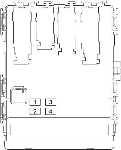
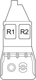
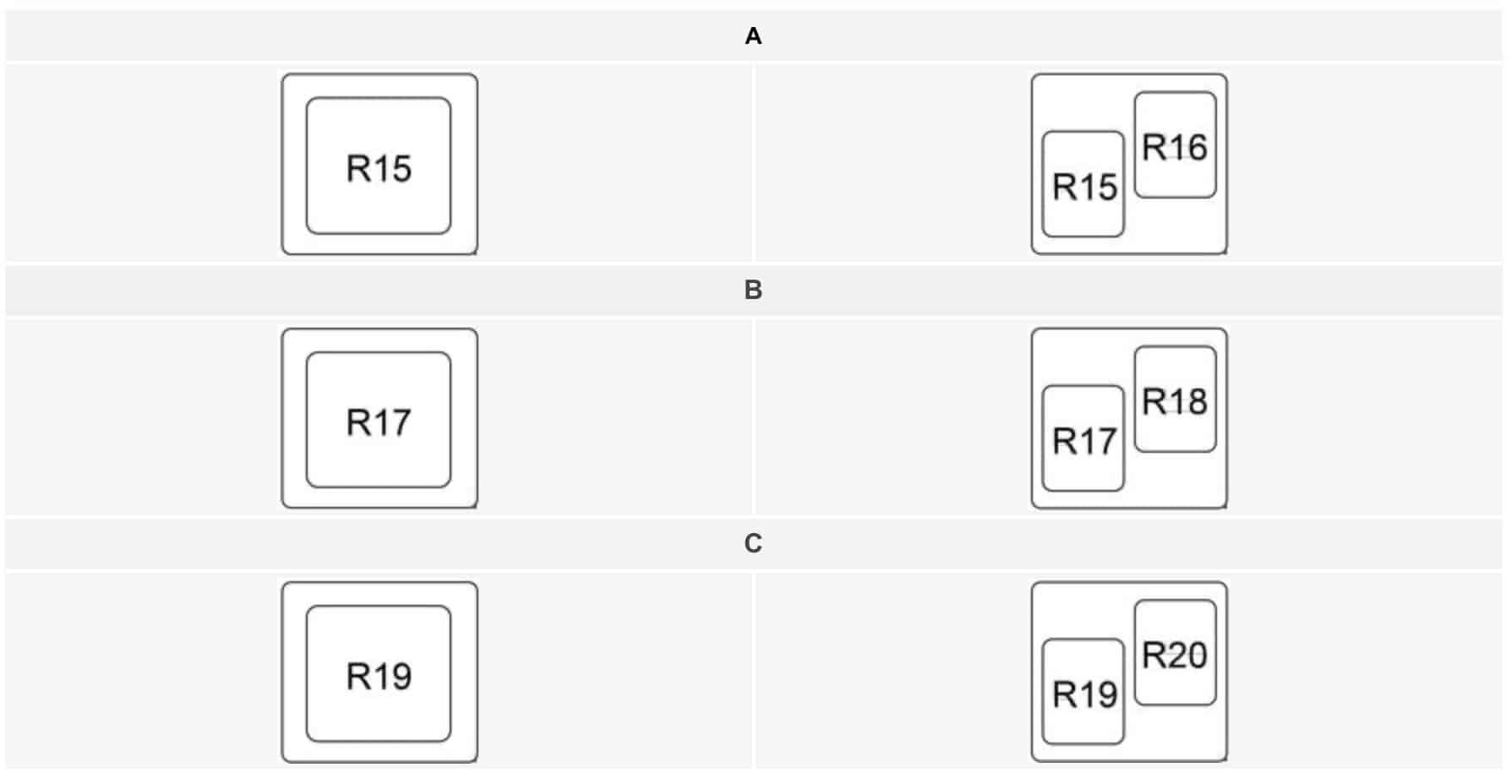
| Relays | ||
| R1 | Not Used | |
| R2 | Cigar Lighter | |
| R3 | Horn | |
| R4 | Rear Window Defogger |
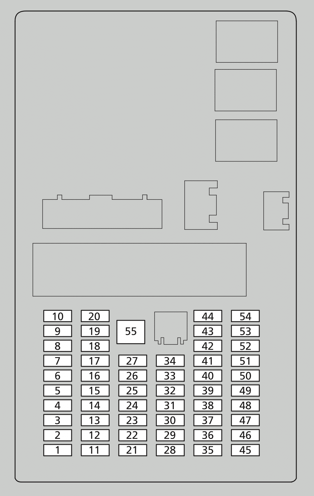
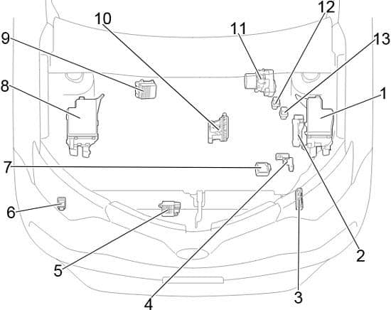
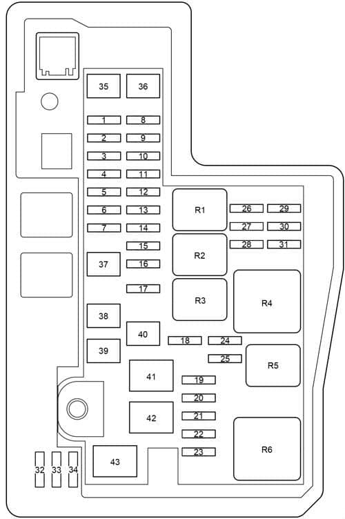
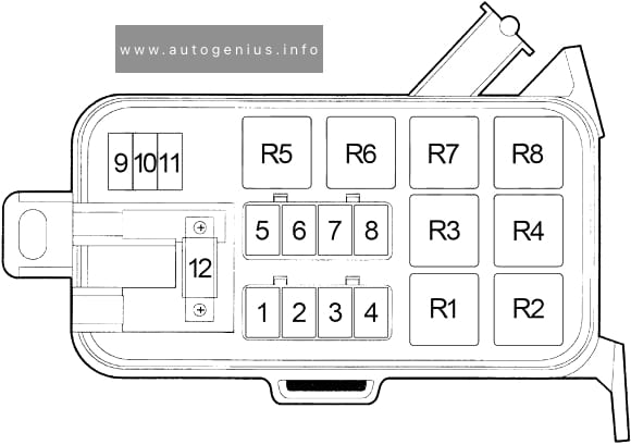
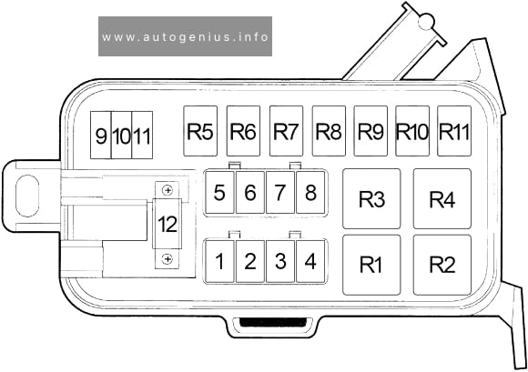
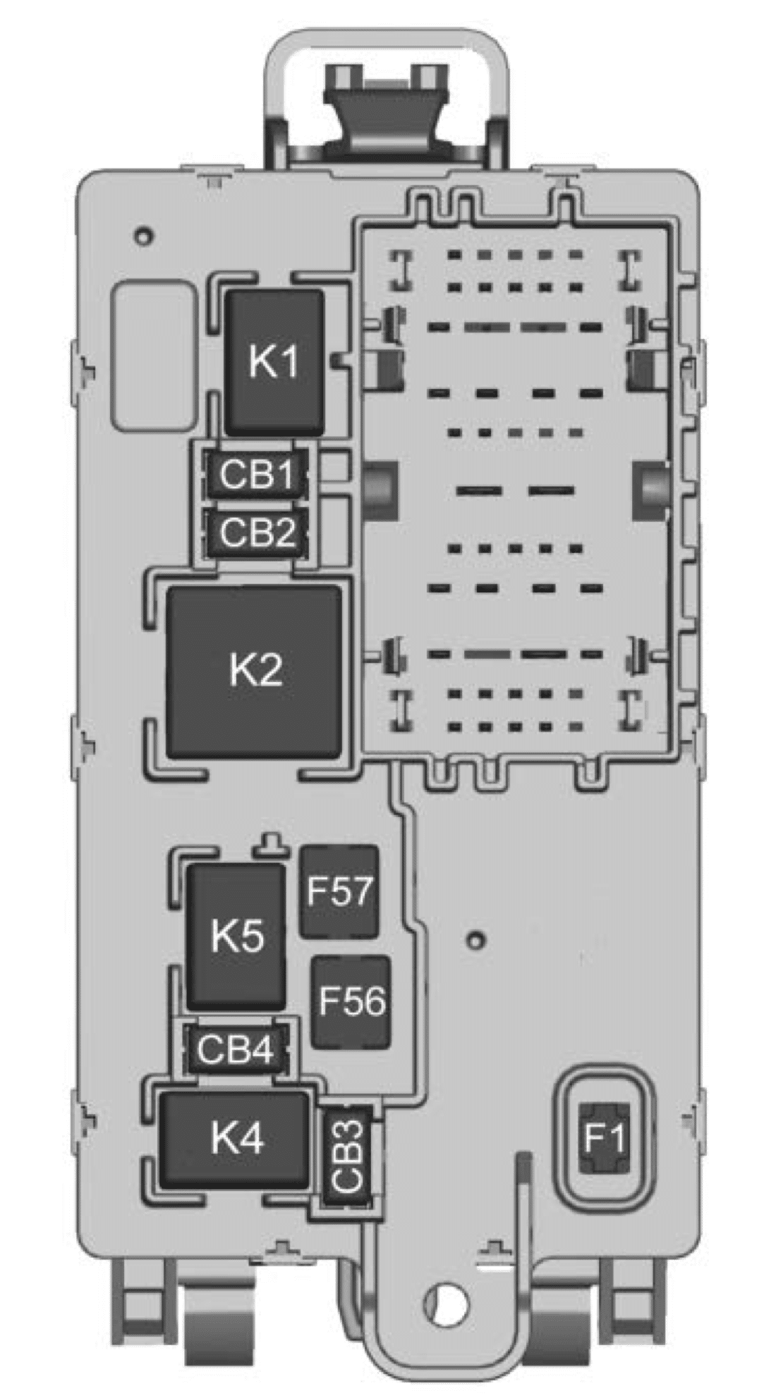
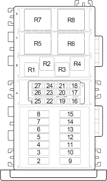
Engine Compartment Fuse Box (Gasoline)
‘00-’01:
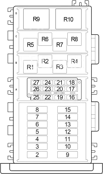
’97-’99:
| No. |
A |
Circuit Protected |
| 1 | – | Not Used |
| 2 | 40 | Ignition Switch (Cigar Lighter Relay, Fuse (Passenger Compartment): “8”, “9”, “10”, “11”, “17”, “18”, “27”, “28”, “30”)) |
| 3 | 40 | Ignition Switch (Fuse (Passenger Compartment): “12”, “19”, “22”, “24”, “25”, “26”)) |
| 4 | 40 or 50 | 1997: Fuse (Passenger Compartment): “1”, “2”, “15”, “20”, “21”, “29” (40A);
1998-2001: Fuse (Passenger Compartment): “1”, “2”, “15”, “20”, “21”, “29” (50A) |
| 5 | 40 | Radiator Fan Relay |
| 6 | 40 | Blower Motor Relay |
| 7 | 30 | Headlamp Switch, Headlamp Delay Module, Daytime Running Lamp Module |
| 8 | 30 | 2000-2001: Automatic Shut Down Relay |
| 9 | 20 | Air Conditioner Compressor Clutch Relay, Fuse (Engine Compartment): “27” (2000-2001), “26” (1997-1999) |
| 10 | 20 or 30 | 1997-1998: Starter Relay, Rear Window Defogger Relay, Fuse (Passenger Compartment): “13” (30A);
1999-2001: Starter Relay (20A) |
| 11 | 30 | 1998-2001: Rear Window Defogger Relay, Fuse (Passenger Compartment): “13” |
| 12 | 40 | ABS |
| 13 | 20 | ABS |
| 14 | – | Not Used |
| 15 | – | Not Used |
| 16 | 15 | Dome Lamp, Cargo Lamp, Instrument Cluster, Courtesy Lamp, Radio, Transmission Control Module, Underhood Lamp, Visor/Vanity Lamp, Overhead Console, Remote Keyless Entry Module, Glove Box Lamp, Compass, Left Front Power Lock/Window Switch (1997 LHD), Right Front Power Lock/Window Switch (1997 LHD) |
| 17 | 20 | 1997-1999: Headlamp Switch, Data Link Connector, Rear Fog Lamp Relay (1997), Power Antenna Relay (1998-1999);
2000-2001: Oxygen Sensor Downstream Relay, Oxygen Sensor Upstream Relay |
| 18 | 15 | 2000-2001: Fuel Injectors, Coil Rail, Coil Capacitor |
| 19 | 20 or 25 | 1997-1999: Automatic Shut Down Relay (25A)
2000-2001: Headlamp Switch, Data Link Connector, Power Antenna Relay (20A) |
| 20 | 15 | Combination Flasher |
| 21 | 15 or 20 | 1997-1999: Fuel Injectors, Ignition Coil, Powertrain Control Module (20A)
2000-2001: Powertrain Control Module (15A) |
| 22 | 15 | Fuel Pump Relay, Powertrain Control Module |
| 23 | 15 | Stop Lamp Switch |
| 24 | 15 | 1997-1999: Oxygen Sensor Downstream, Oxygen Sensor Upstream |
| 25 | 15 | Fog Lamp Relay №2 (1998-2001), Fog Lamp Relay (1997-1999) |
| 26 | 20 | Power Amplifier |
| 27 | 10 | Sentry Key Immobilizer Module |
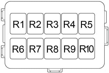
| Relays | ||
| R1 | Air Conditioner Compressor Clutch | |
| R2 | 1997-1999: Fog Lamp; 1998-2001: Fog Lamp No.1 |
|
| R3 | 1998-2001: Fog Lamp No.2 | |
| R4 | ABS | |
| R5 | 1997-1999: Radiator Fan; 2000-2001: Fuel Pump |
|
| R6 | 1997-1999: Automatic Shut Down; 2000-2001: Starter |
|
| R7 | 1997-1999: Starter; 2000-2001: Oxygen Sensor Upstream |
|
| R8 | 1997-1999: Fuel Pump; 2000-2001: Oxygen Sensor Downstream |
|
| R9 | 2000-2001: Radiator Fan | |
| R10 | 2000-2001: Automatic Shut Down |
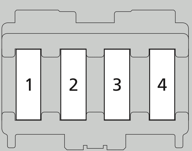
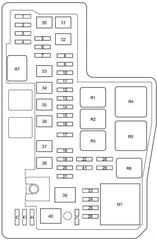
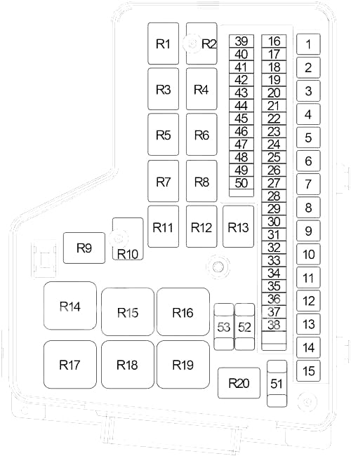
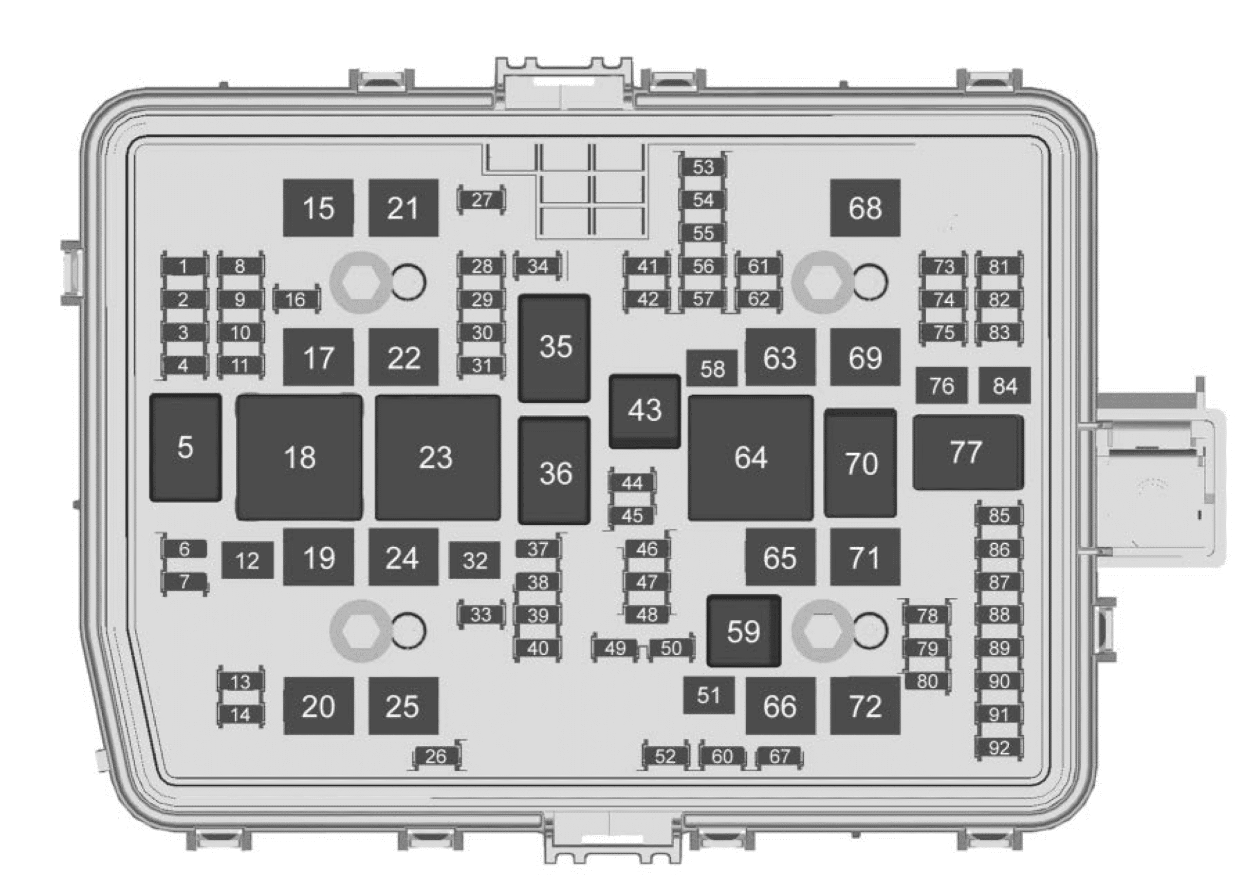
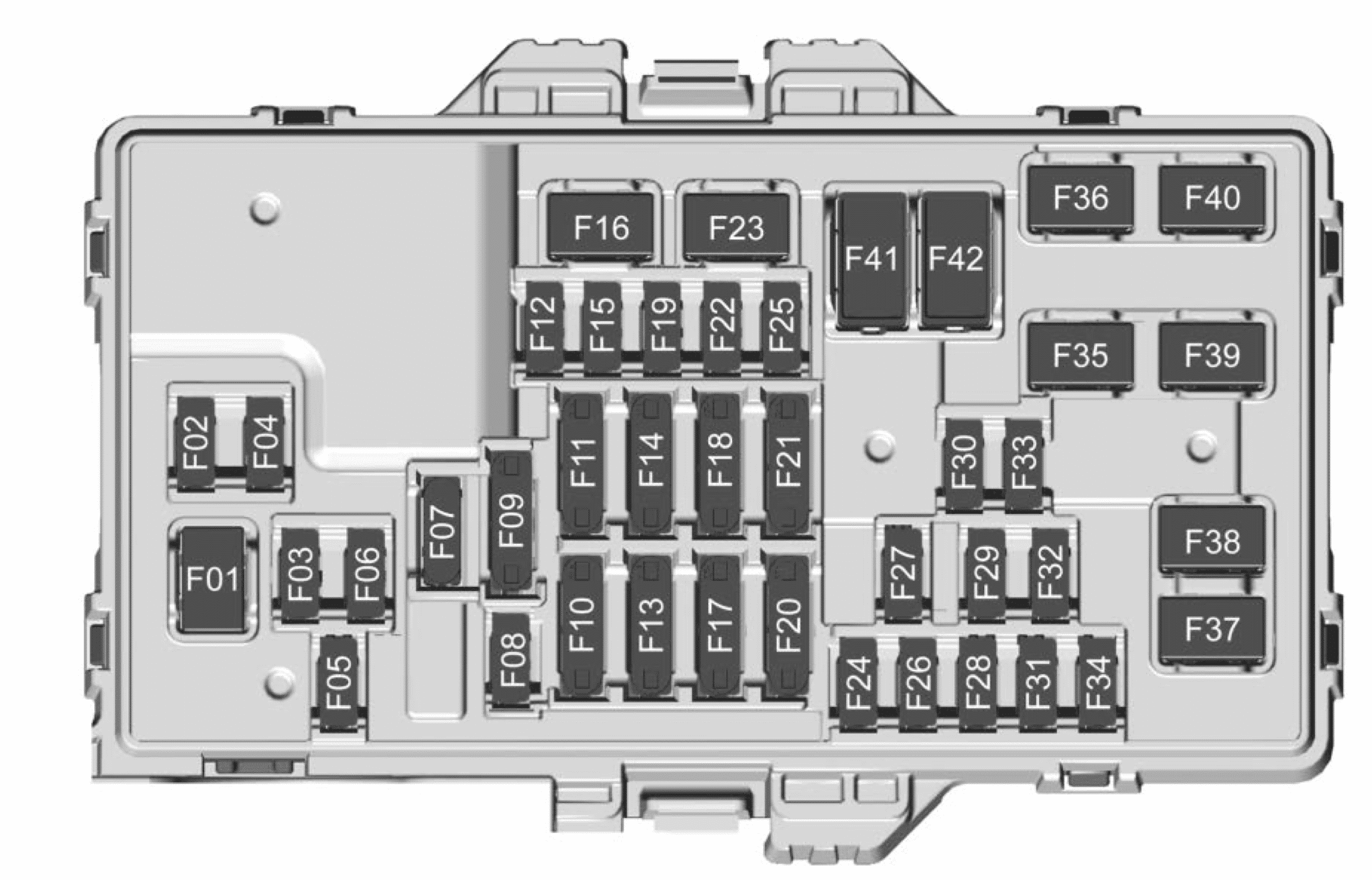
Fuse Box Diagram (Diesel)
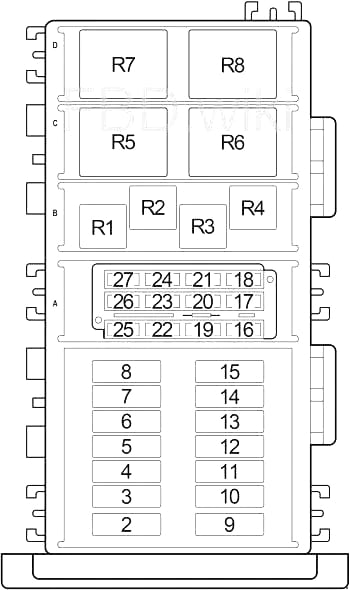
| No. |
A |
Circuit Protected |
| 1 | – | Not Used |
| 2 | 50 | Glow Plug Relay |
| 3 | 50 | Glow Plug Relay |
| 4 | 30 | 1997-1998: Diesel Power Relay (Fuel Pump Module, Powertrain Control Module, Generator, Fuse (Engine Compartment): “21”), Fuse (Engine Compartment): “24”;
1999-2001: Automatic Shut Down Relay (Engine Control Module, Fuel Injection Pump, Powertrain Control Module, Radiator Fan Relay, Air Conditioner Compressor Clutch Relay), Fuse (Engine Compartment): “24” |
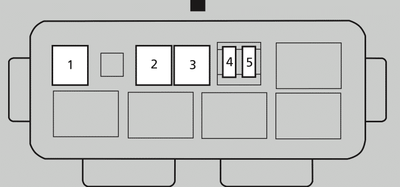
| 5 | 40 | Ignition Switch (Cigar Lighter Relay, Fuse (Passenger Compartment): “8”, “9”, “10”, “11”, “17”, “18”, “27”, “28”, “30”)) |
| 6 | 30 | Fuel Heater Relay |
| 7 | 20 or 30 | 1997-1998: Starter Relay, Rear Window Defogger Relay, Fuse (Passenger Compartment): “13” (30A);
1999-2001: Starter Relay (20A) |
| 8 | 30 | Headlamp Switch, Headlamp Delay Module |
| 9 | 50 | Fuse (Passenger Compartment): “1”, “2”, “15”, “20”, “21”, “29” |
| 10 | 40 | Ignition Relay (Fuse (Passenger Compartment): “12”, “19”, “22”, “24”, “25”, “26”)) |
| 11 | 40 | Blower Motor Relay |
| 12 | 40 | ABS |
| 13 | 40 | Radiator Fan Relay (1998-2001) |
| 14 | 20 | ABS |
| 15 | 30 | Rear Window Defogger Relay, Fuse (Passenger Compartment): “13” (1999-2001) |
| 16 | 15 | Dome Lamp, Cargo Lamp, Instrument Cluster, Courtesy Lamp, Radio, Transmission Control Module, Underhood Lamp/Mercury Switch, Visor/Vanity Lamp, Overhead Console, Remote Keyless Entry Module, Glove Box Lamp, Compass, Left Front Power Lock/Window Switch (1997 LHD), Right Front Power Lock/Window Switch (1997 LHD) |
| 17 | – | Not Used |
| 18 | – | Not Used |
| 19 | 15 | Stop Lamp Switch |
| 20 | 20 | Air Conditioner Compressor Clutch Relay, Fuse (Engine Compartment): “27” |
| 21 | 20 | 1997-1998: Glow Plug Relay, Mass Air Flow Sensor, Fuel Pump Module, Electronic Vacuum Modulator, Air Conditioner Compressor Clutch Relay
1999-2001: Fuel Injection Pump, Glow Plug Relay, EGR Solenoid |
| 22 | 20 | Power Amplifier |
| 23 | 15 | Combination Flasher |
| 24 | 10 | Powertrain Control Module |
| 25 | 15 | Fog Lamp Relay |
| 26 | 20 | Headlamp Switch, Data Link Connector, Power Antenna Relay (1998-2001), Rear Fog Lamp Relay (1997) |
| 27 | 10 | Sentry Key Immobilizer Module (1998-2001), Overhead Module (1997) |
| Relays | ||
| R1 | Air Conditioner Compressor Clutch | |
| R2 | Fog Lamp (1997-1999) | |
| R3 | Fog Lamp (2000-2001) | |
| R4 | ABS | |
| R5 | Radiator Fan | |
| R6 | 1997-1999: Diesel Power; 2000-2001: Automatic Shut Down |
|
| R7 | Starter | |
| R8 | Fuel Heater |
WARNING: Terminal and harness assignments for individual connectors will vary depending on vehicle equipment level, model, and market.