Chevrolet Silverado mk3 (Third Generation) 2014 – 2015 – fuse box diagram
Year of production: 2014, 2015
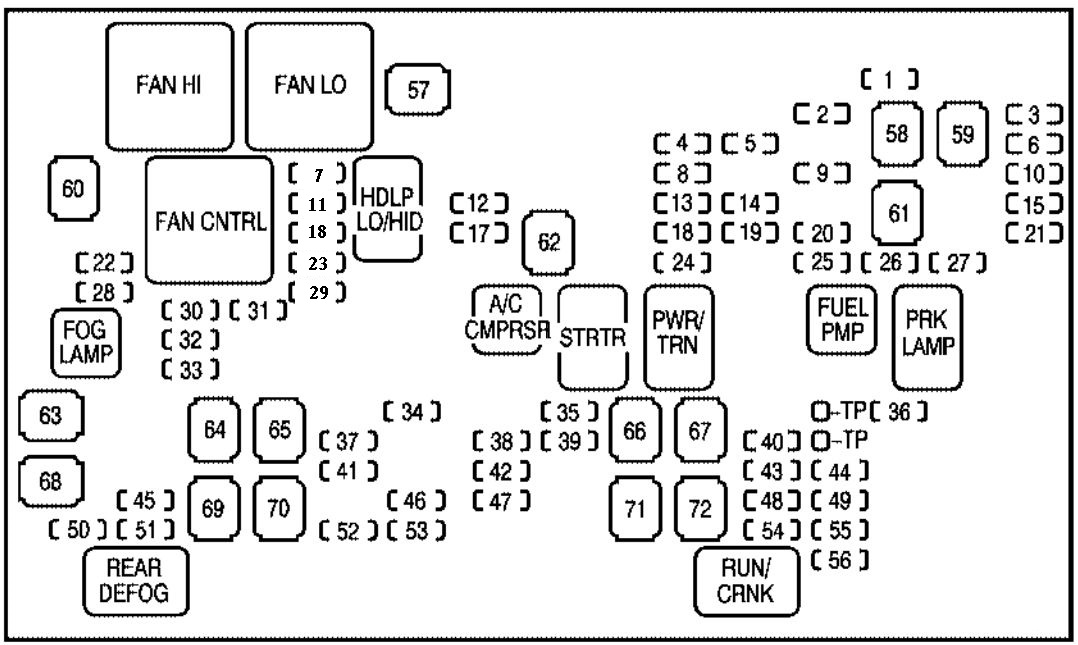
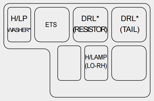
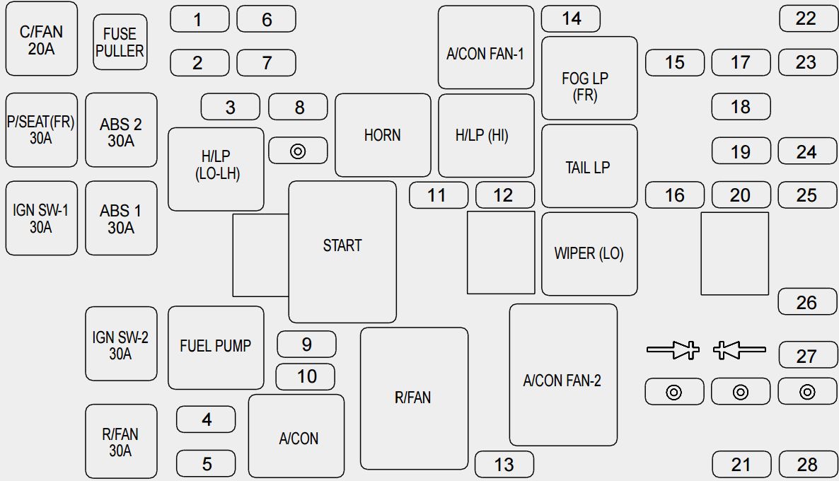
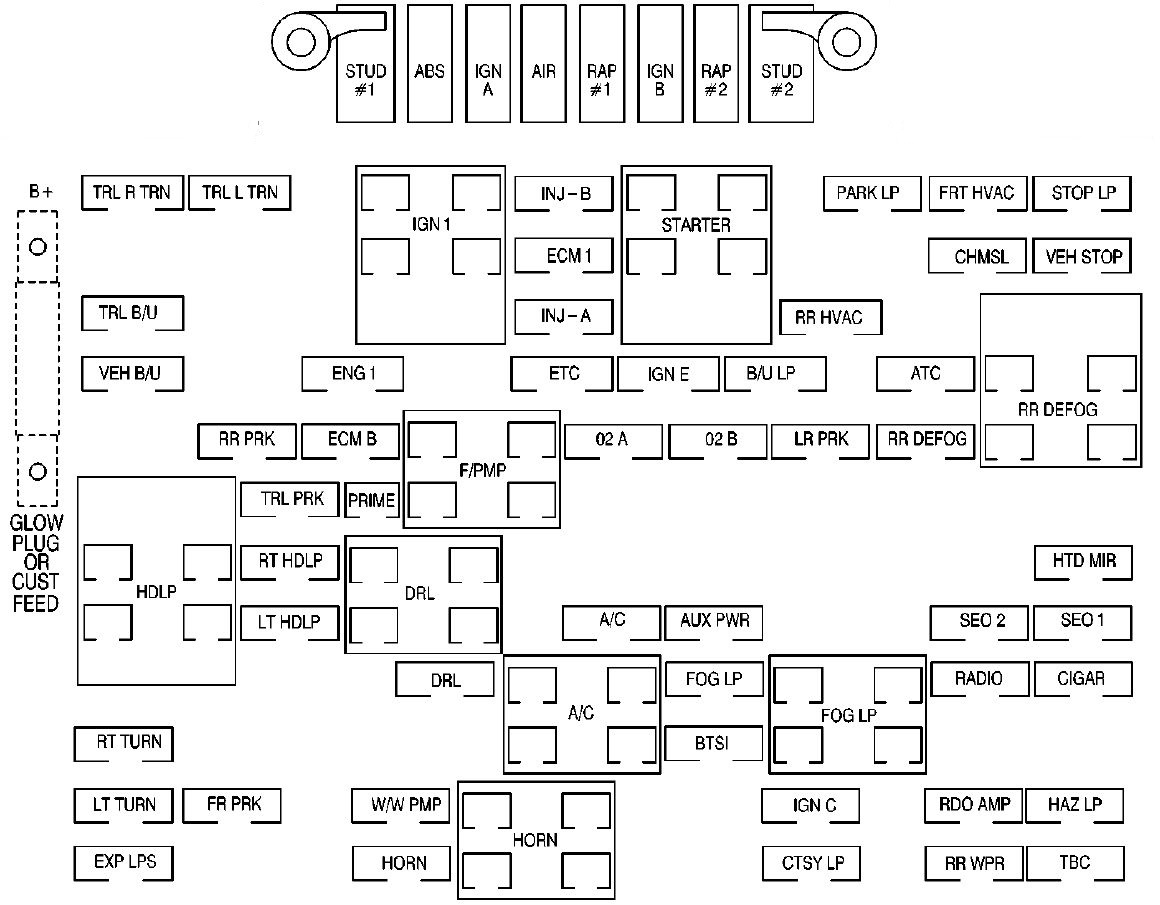
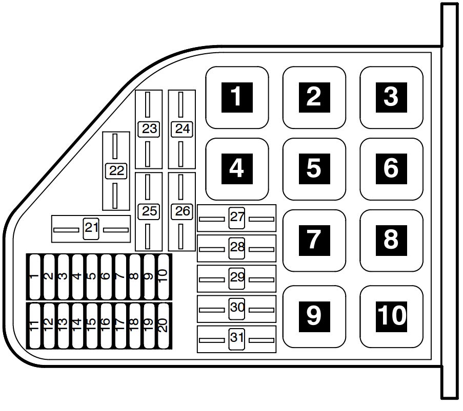
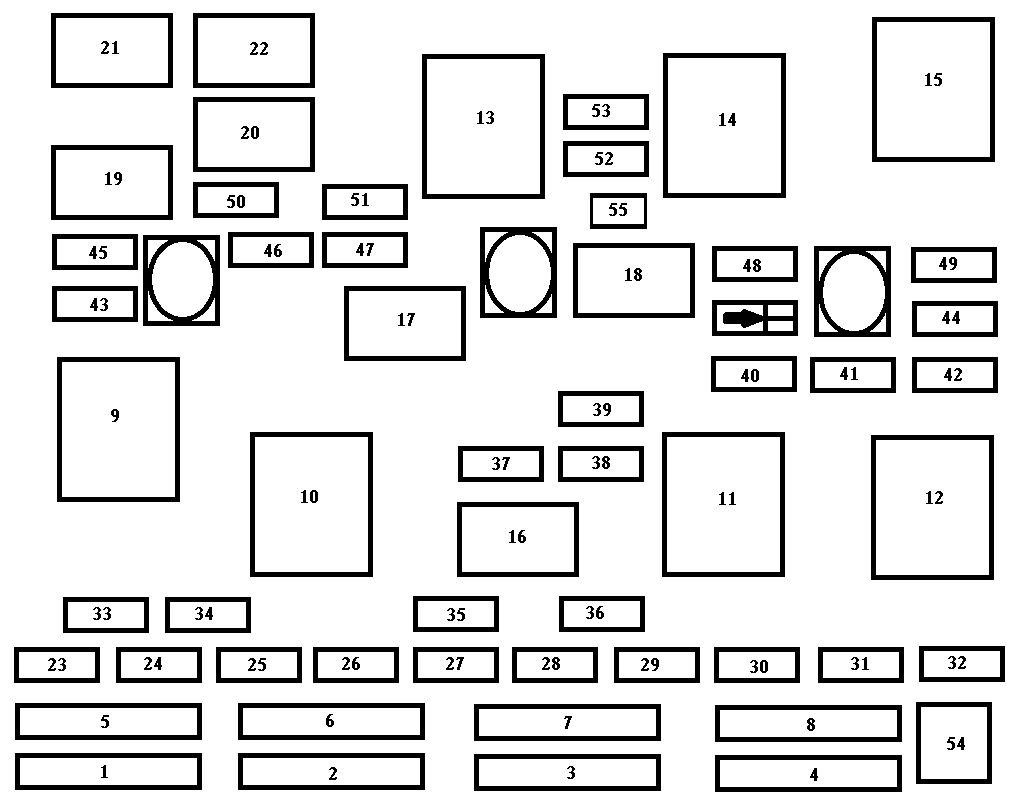
Engine Compartment Fuse Block
The engine compartment fuse block is in the engine compartment, on the driver side of the vehicle.
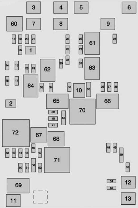
| Micro J-Case Fuses | Usage |
| 1 | Trailer Brake |
| 2 | Trailer Battery |
| J-Case Fuses | Usage |
| 3 | Antilock Brake System Pump |
| 4 | Instrument Panel BEC 1 |
| 5 | Spare |
| 6 | 4WD Trec |
| 7 | Spare |
| 8 | Instrument Panel BEC 2 |
| 9 | Spare |
| 10 | Rear Window Defogger |
| 11 | Starter |
| 12 | Cooling Fan 1 |
| 13 | Cooling Fan 2 |
| Mini Fuses (2 Pin) | Usage |
| 14 | Trailer Stop/Turn Lamps, Left |
| 15 | Trailer Parking Lamps |
| 16 | Trailer Back-up Lamp |
| 17 | Trailer Stop/Turn Lamps, Right |
| Micro Fuses (2 Pin) | Usage |
| 18 | Fuel Pump |
| 19 | Integrated Chassis Control Module |
| 20 | Electronic Suspension Control Module |
| 21 | Fuel Pump Power Module |
| 22 | Upfitter Switch 1 |
| 23 | Upfitter 2 |
| 24 | Front Wiper |
| 25 | Antilock Brake System Valves |
| 26 | Upfitter SW 2 |
| 27 | Upfitter SW 3 |
| 28 | Parking Lamps, Right |
| 29 | Parking Lamps, Left |
| 30 | Upfitter 3 |
| 31 | Upfitter SW 4 |
| 32 | Upfitter 4 |
| 33 | Back-up Lamps |
| 34 | Engine Control Module Ignition |
| 35 | Air Conditioning Compressor Clutch |
| 36 | Heated Mirrors |
| 37 | Upfitter 1 |
| 38 | Center High-Mounted Stoplamp |
| 39 | Miscellaneous Ignition |
| 40 | Transmission Ignition |
| 41 | Fuel Pump 2 |
| 42 | Cooling Fan Clutch |
| 43 | Engine |
| 43 | Fuel Injectors A, Odd |
| 45 | Fuel Injectors B, Even |
| 46 | Oxygen Sensor B |
| 47 | Throttle Control |
| 48 | Horn |
| 49 | Fog Lamp |
| 50 | Oxygen Sensor A |
| 51 | Engine Control Module |
| 52 | Interior Heater |
| 53 | Spare |
| 54 | Aeroshutter |
| 55 | Front Washer |
| Micro Fuses (3 Pin) | Usage |
| 56 | Air Conditioning Compressor/ Battery Regulated Voltage Control |
| 57 | Air Conditioning Compressor Module/ Battery Pack |
| 58 | Transmission Control Module/ Engine Control Module |
| 59 | Headlamps |
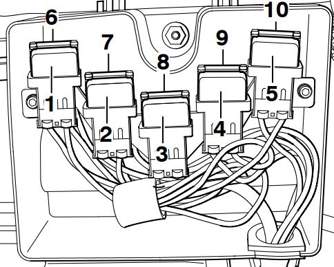
| Micro Relays | Usage |
| 60 | Fuel Pump |
| 61 | Upfitter 2 |
| 62 | Upfitter 3 |
| 63 | Upfitter 4 |
| 64 | Trailer Parking Lamps |
| 65 | Run/Crank |
| 66 | Upfitter 1 |
| 67 | Fuel Pump 2 |
| 68 | Air Conditioning Control |
| 69 | Starter |
| Mini Relays | Usage |
| 70 | Rear Window Defogger |
| 71 | Engine Control Module |
| Solid State Relay | Usage |
| 72 | Cooling Fan Clutch |
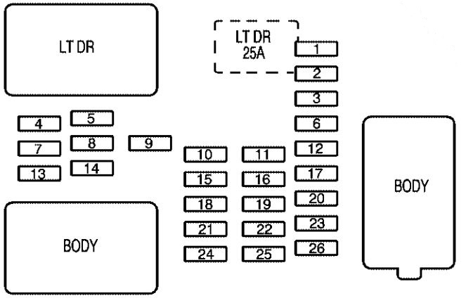
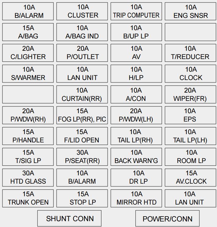
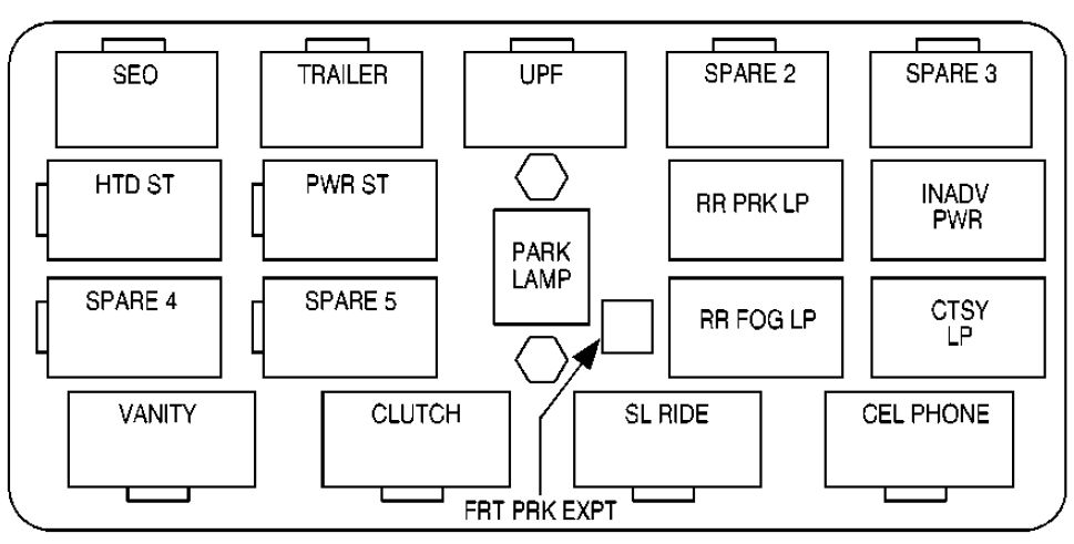
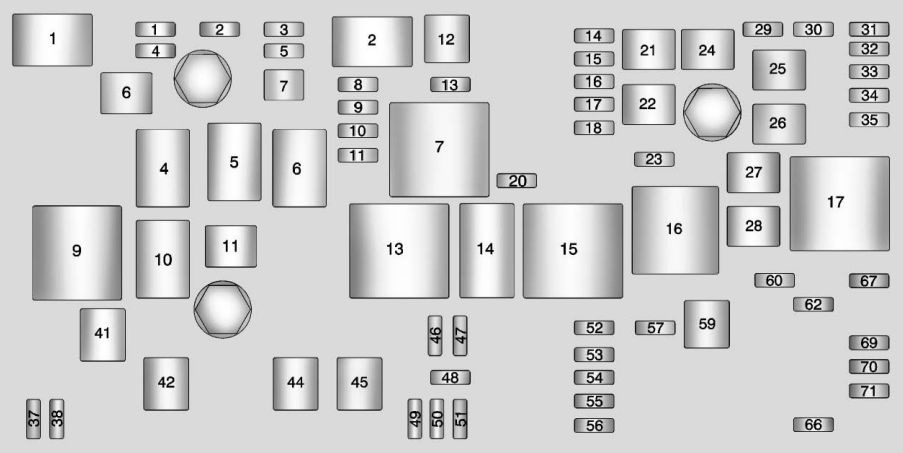
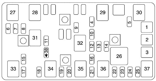
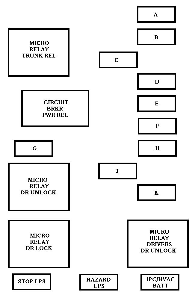
Instrument Panel Fuse Block (Left)
The left instrument panel fuse block access door is on the driver side edge of the instrument panel.
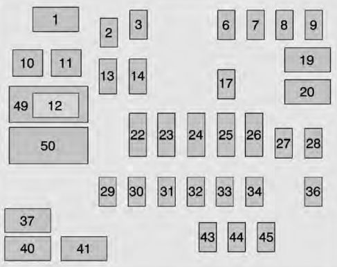
| Number | Usage |
| 1 | Accessory Power Outlet 2 |
| 2 | SEO Retained Accessory Power |
| 3 | Universal Garage Door Opener/Inside Rearview Mirror |
| 6 | Body Control Module 3 |
| 7 | Body Control Module 5 |
| 8 | Driver Window Switch/Mirror Switch |
| 9 | Spare |
| 10 | Accessory Power Outlet Retained Accessory Power |
| 11 | Accessory Power Outlet Battery |
| 12 | Accessory Power Outlet 1/Cigarette Lighter |
| 13 | Discrete Logic Ignition Switch |
| 14 | Switch Backlighting |
| 17 | Body Control Module 1 |
| 19 | Spare |
| 20 | spare |
| 22 | Heater, Ventilation, and Air Conditioning/ Auxiliary Heater, Ventilation and Air Conditioning Ignition |
| 23 | Instrument Cluster Ignition/Sensing Diagnostic Module Ignition |
| 24 | Spare |
| 25 | Data Link Connector/ Driver Seat Module |
| 26 | Passive Entry Passive Start/Heater, Ventilation, and Air Conditioning |
| 27 | Spare |
| 28 | Spare |
| 29 | Park Enable/ Electrically Adjustable Pedals |
| 30 | SEO |
| 31 | Accessory/Run Crank |
| 32 | Heated Steering Wheel |
| 33 | Spare |
| 34 | Instrument Cluster |
| 36 | Spare |
| 37 | Spare |
| 40 | Left Doors |
| 41 | Driver Power Seat |
| 43 | Left Front Heated/ Cooled Seat |
| 44 | Right Front Heated/ Cooled Seats |
| 45 | Spare |
| 49 | Retained Accessory Power/Accessory |
| 50 | Run/Crank |
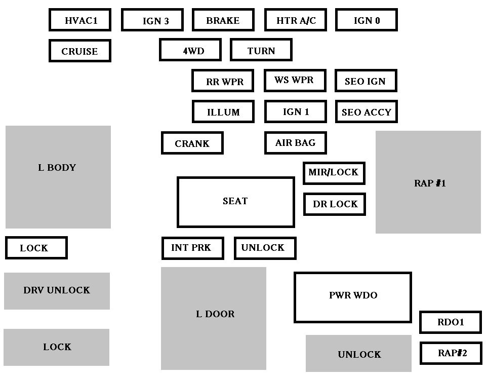
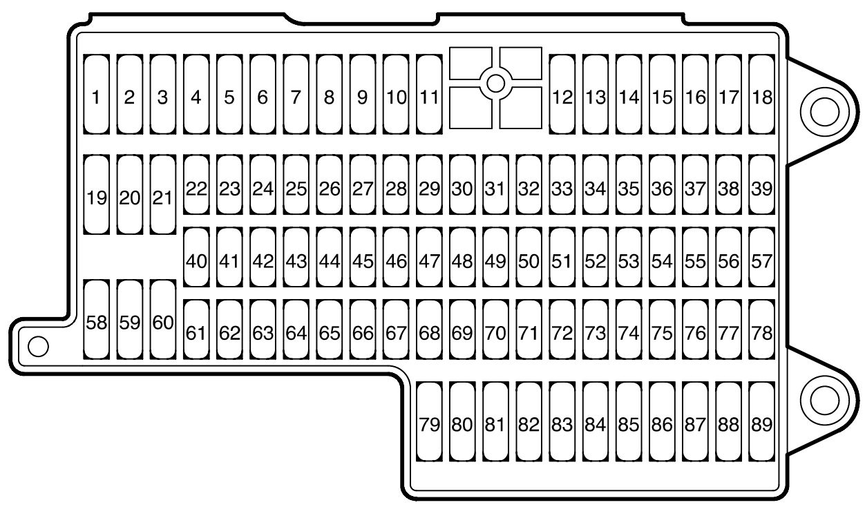
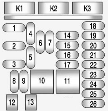
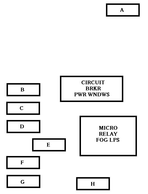
Instrument Panel Fuse Block (Right)
The right instrument panel fuse block access door is on the passenger side edge of the instrument panel.
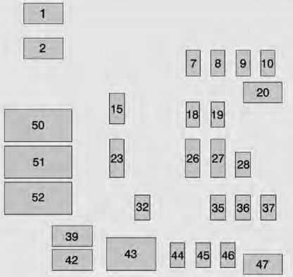
| Number | Usage |
| 1 | Accessory Power Outlet 3 |
| 2 | Accessory Power Outlet 4 |
| 7 | Body Control Module 4 |
| 8 | Body Control Module 8 |
| 9 | Rear Seat Entertainment |
| 10 | Cargo Lamp |
| 15 | Steering Wheel Controls |
| 18 | Radio |
| 19 | Spare |
| 20 | Sunroof |
| 23 | Airbag/Info |
| 26 | Export/Power Take Off/SEO Battery 1 |
| 27 | Obstacle Detection/ USB Ports |
| 28 | Body Control Module 2 |
| 32 | SEO Battery 2 |
| 35 | AC Inverter |
| 36 | Amplifier |
| 37 | Spare |
| 39 | Rear Sliding Window |
| 42 | Right Door Window Motor |
| 43 | Front Blower |
| 44 | SEO |
| 45 | Body Control Module 6 |
| 46 | Body Control Module 7 |
| 47 | Passenger Seat |
| 50 | Retained Accessory Power/Accessory |
| 51 | Rear Sliding Window Open |
| 52 | Rear Sliding Window Close |
WARNING: Terminal and harness assignments for individual connectors will vary depending on vehicle equipment level, model, and market.