VW Beetle (1954 – 1979) – fuse and relay box diagram
Year of production: 1954, 1955, 1956, 1957, 1958, 1959, 1960, 1961, 1962, 1963, 1964, 1965, 1966, 1967, 1968, 1969, 1970, 1971, 1972, 1973, 1974, 1975, 1976, 1977, 1978, 1979
The classic compact car Volkswagen Beetle was produced from 1938 to 2003. In this article, you will find fuse box diagrams for the Volkswagen Beetle models from 1954 through 1979, get information about the location of the fuse panels inside the vehicle, and learn about the assignment of each fuse (fuse layout) and relay.
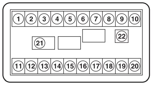
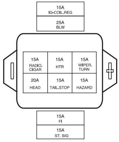
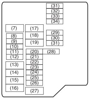
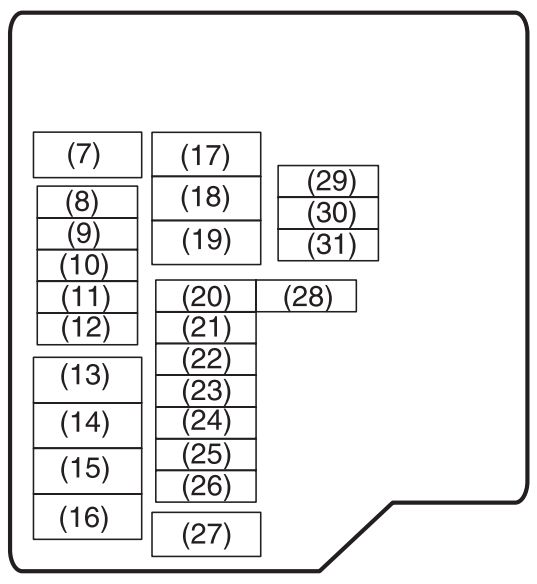
Fuse box diagram
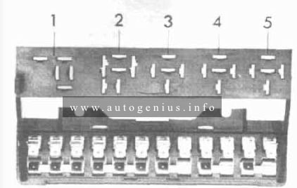
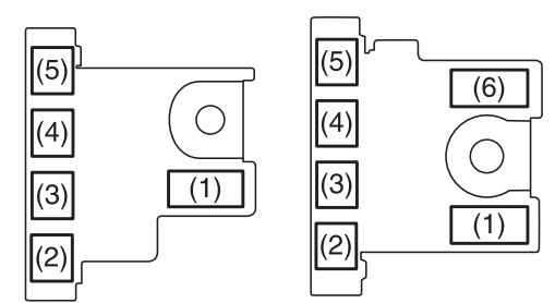
Assignment of the fuses in the fuse box
| Fuse/relay | Description |
| 1 | Low beam |
| 2 | Open |
| 3 | Turn signal/emergency flasher |
| 4 | Open |
| 5 | Buzzer |
WARNING: Terminal and harness assignments for individual connectors will vary depending on vehicle equipment level, model, and market.