KIA Borrego (2017) – fuse box diagram
Year of production: 2017
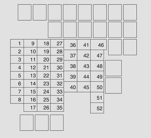
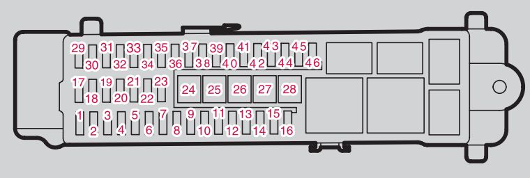
Inner fuse panel (Instrument panel)
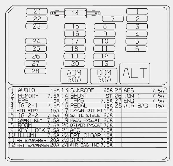
| Description | Fuse rating | Protected component |
| AUDIO | 15 | Audio, A/V & Navigation Head Unit, MTS E-Call Module |
| MEMORY | 7,5 | Front/Rear A/C Control Module, Instrument Cluster(IND.), FAM, RAM, Driver/Passenger Door Module, IMS Control Module, Tilt & Telescopic Module, RF Receiver |
| IG2-1 | 7,5 | Front A/C Control Module, Multifunction Switch, Driver/Passenger Seat Warmer Module, Rain Sensor, Around View Monitor, Smart Key Control Module, Relay Block(Front/Rear Blower Relay), E/R Sub Block (COOLING FAN2 Relay, Fuel Heater Relay), Driver/Passenger CCS Control Module |
| HEATED S/WHEEL | 15 | Steering Wheel Heated |
| IG2-2 | 7,5 | Rear A/C Control Module, Driver/Passenger Door Module, FAM |
| OBD-II | 7,5 | Start Stop Button Switch |
| ROOM | 7,5 | Hazard Switch, Map Lamp, Vanity Lamp Switch LH/RH, Front/Rear A/C Control Module, Center Room Lamp, Rear Room Lamp |
| K/LOCK | 7,5 | Sport Mode Switch, Driver/Passenger Door Module, Ignition Key Interlock |
| ILLUMI | 7,5 | IPM |
| RR S/WARMER | 20 | Rear Seat Warmer Relay |
| SEAT WARMER | 20 | Driver Seat Warmer Module, Passenger Seat Warmer Module, Driver / Passenger CCS Control Module |
| SUNROOF | 25 | Sunroof Module |
| TPMS | 7,5 | Tire Pressure Monitoring Module |
| S/TILT | 20 | Tilt & Telescopic Module |
| PASS P/SEAT | 20 | Passenger Power Seat Switch |
| DRIVER P/SEAT | 30 | Driver Power Seat Switch, Lumbar Support Switch, IMS Control Module |
| ACC | 7,5 | Audio, A/V & Navigation Head Unit, MTS E-Call Module, Smart Key Control Module, Around View Monitor, JBL AMP |
| FRT CIGAR | 15 | Cigarette Lighter |
| START | 7,5 | Burglar Alarm Relay, Start Relay |
| AIR BAG IND | 7,5 | Instrument Cluster (Air Bag IND.) |
| ABS | 7,5 | ABS Control Module, ESC Control Module, DBC Relay, Steering Angle Sensor, Crash Pad Switch |
| IGN 1 | 7,5 | Rheostat, Air Suspention Control Module, Electro Chromic Mirror, Front Wiper Motor, Smart Key Control Module, Multipurpose Check Connector, MTS E-Call Module, Rear Parking Assist Buzzer, Rear Parking Assist Switch, Sport Mode Switch, Audio, A/V & Navigation Head Unit, Stop Lamp Switch, Auto Head Lamp Leveling Device Sensor, Alternator, Multifunction Switch, Tire Pressure Monitoring Module, Blind Spot Detection Radar LH/RH, Tilt & Telescopic Module, Front A/C Control Module, Instrument Cluster, Fuel Filter Warning Switch, Lane Departure Warning Control Module, Front/Rear Parking Assist Sensor LH/RH, Front/Rear Parking Assist Sensor Center LH/RH |
| ENG | 7,5 | ECM, TCM, 4WD ECM, Air Flow Sensor, Smart Key Control Module, Inhibitor Switch, Multipurpose Check Connector |
| AIR BAG | 15 | SRS Control Module |
| DDM | 30 | Driver Door Module, Driver Safety Power Window Motor |
| ADM | 30 | Assistant Door Module, Passenger Safety Power Window Motor |
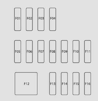
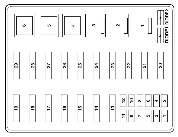
Inner fuse panel (Luggage compartment)
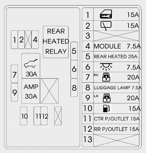
| Fuse | Fuse rating | Circuit protected |
| D/LOCK | 15 | Rear Door Lock/Unlock Relay |
| RR WIPER | 15 | Rear Wiper Motor Relay |
| MODULE 1 | 7,5 | Console Switch LH/RH |
| RR DEFOG | 25 | RR Defog Relay |
| RR P/WIN-RH | 20 | Rear Power Window Relay RH(UP/DN) |
| LUGGAGE | 7,5 | Luggage Lamp |
| RR P/WIN-LH | 20 | Rear Power Window Relay LH(UP/DN) |
| FUEL DR | 15 | Fuel Door Relay |
| CONSOL P/OUT | 15 | Console Power Outlet |
| RR P/OUT | 15 | Rear Power Outlet |
| T/G POWER LATCH | 30 | Tail Gate Control Module |
| AMP | 30 | JBL AMP |
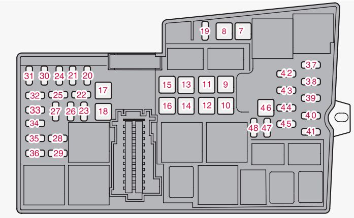
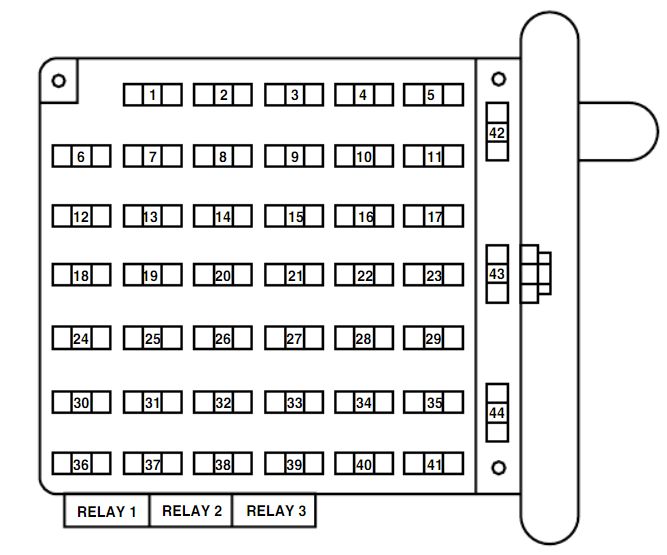
Engine compartment main fuse panel
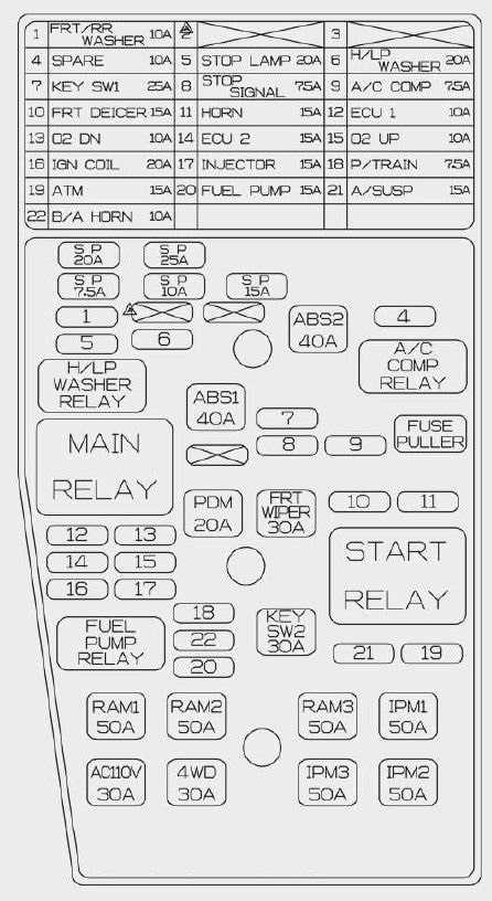
| Description | Fuse rating | Protected component |
| FRT/RR WASHER | 10 | Front/Rear Washer Motor Relay |
| STOP LAMP | 20 | FAM(STOP SIGNAL 7.5A), DBC Relay, Stop Signal Relay |
| KEY SW 1 | 25 | Ignition Switch, PDM Relay Box (IG1 Relay , ACC Relay) |
| STOP SIGNAL | 7,5 | Stop Lamp Switch, Smart Key Control Module |
| A/C COMP | 7,5 | A/C Comp Relay |
| FRT DEICER | 15 | Front Deicer Relay |
| HORN | 15 | Horn Relay |
| ECU 1 | 10 | DIESEL – Immobilizer Module, A/C Comp Relay, Stop Lamp Switch, E/R Sub Block (Glow Relay, PTC 1~3 Relay), Lambda Sensor GASOLINE – ECM, Mass Air Flow Sensor, Immobilizer Module, A/C Comp Relay |
| O2 DN | 10 | GASOLINE – Oxygen Sensor #3/ #4 |
| ECU 2 | 15 | DIESEL – EGR Cooling Valve, Electric VGT Actuator / GASOLINE – Oil Control Valve, ECM, Variable Intake Manifold Valve, Purge Control Solenoid Valve |
| O2 UP | 10 | DIESEL – Rail Pressure Regulator Valve, Fuel Meter Unit GASOLINE : Oxygen Sensor #1/ #2 |
| IGN COIL | 20 | GASOLINE – Ignition Coil #1~#6, Condenser #1,#2 |
| INJECTOR | 15 | ECM, Injector #1~#6(GASOLINE) |
| P/TRAIN | 7,5 | ECM, Main Relay |
| FUEL PUMP | 15 | Fuel Pump Relay |
| ATM | 15 | TCM |
| A/SUSP | 15 | Air Suspension Control Module |
| H/LP WASHER | 20 | Head Lamp Washer Motor & Washer Level Sensor |
| B/A HORN | 10 | Relay Box (Burglar Horn Relay) |
| ABS 2 | 40 | ABS Control Module, ESC Control Module, Multipurpose Check Connector |
| ABS 1 | 40 | ABS Control Module, ESP Control Module |
| PDM | 20 | Smart Key Control Module |
| FRT WIPER | 30 | Front Wiper ON Relay |
| KEY SW 2 | 30 | Start Relay #1, Ignition Switch, PDM Relay Box (IG2 Relay) |
| RAM 1 | 50 | RAM(CONSOL P/OUT 15A, RR P/OUT 15A, FUEL DR 15A, RR P/WIN-LH 20A, RR P/WIN-RH 20A, LUGGAGE 7.5A) |
| RAM 2 | 50 | RAM (RR DEFOG 25A, T/G POWER LATCH 30A, DOOR LOCK 15A, RR WIPER 15A, MODULE 1 7.5A) |
| RAM 3 | 50 | RAM(AMP 30A) |
| IPM 1 | 50 | IPM (ILLUMI 7.5A, DDM 30A, SEAT WARMER 20A, OBD-II 7.5A, SUNROOF 25A, K/LOCK 7.5A, TPMS 7.5A) |
| IPM 2 | 50 | IPM (ADM 30A, S/TILT 20A) |
| IPM 3 | 50 | IPM (MEMORY 7.5A, DRIVER P/SEAT 30A, PASS P/SEAT 20A, RR S/WARM 20A, ROOM 7.5A, AUDIO 15A) |
| 4WD | 30 | 4WD ECM |
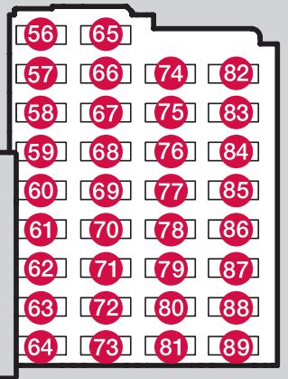
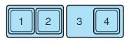
Engine compartment sub fuse panel
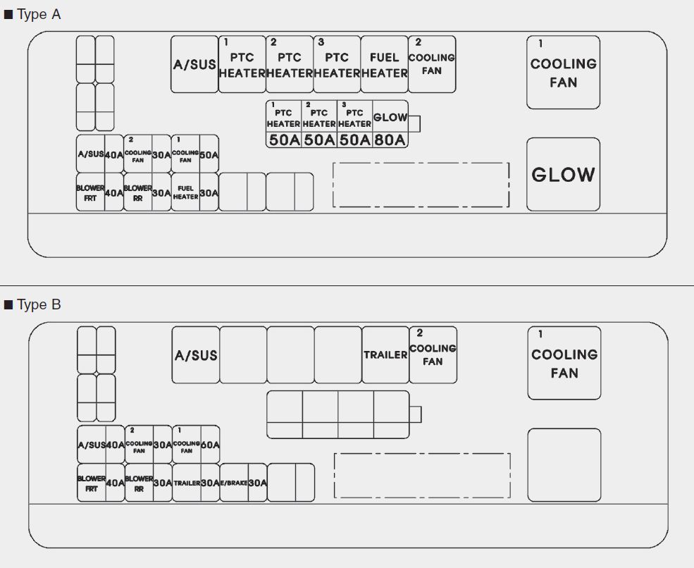
| Description | Fuse rating | Protected components |
| COOLING FAN 2 | 30 | COOLING FAN 2 RELAY |
| FUEL HEATER | 30 | FUEL HEATER RELAY |
| A/SUS | 40 | AIR SUPENSION RELAY |
| BLOWER FRT | 40 | RELAY BLOCK(FRONT BLOWER RELAY) |
| BLOWER RR | 30 | RELAY BLOCK(REAR BLOWER RELAY) |
| PTC HEATER 1 | 50 | PTC 1 RELAY |
| PTC HEATER 2 | 50 | PTC 2 RELAY |
| PTC HEATER 3 | 50 | PTC 3 RELAY |
| COOLING FAN 1 | 50 | COOLING FAN 1 RELAY |
| GLOW | 80 | GLOW RELAY |
WARNING: Terminal and harness assignments for individual connectors will vary depending on vehicle equipment level, model, and market.