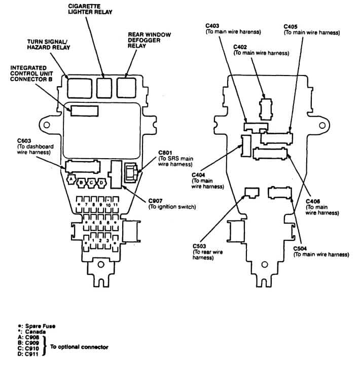
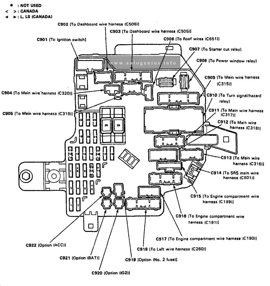
Back-up lights, Gauge assambly, Clock, Vehicle speed sesnsor (VSS), Shift lock solenoid, Integrated control unit, Moonroof open relay, Moonroof close relay
2
FUEL PUMP
15
PGM·FI main relay, SRS unit
3
SRS
10
SRS unit
4
ECU, CRUISE CONTROL, EAT ECU
15
Cruise control system, Transmission control module (TCM), Security control unit, Radiator fan control module, Alternator, PGM-FI, ELD unit
20 (’97 model)
5
TURN SIGNAL
7,5
Turn signal/hazard relay
6
WIPER WASHER
30
Windshield wiper motor
7
HEATER, CONTROL RELAY
7,5
Climate control unit, Mode control motor, Recirucation control module, Blower motor relay, Blower motor high relay, Water valve control solenoid valve, Option connector (C909)
Power mirrors, A/C compressor clutch, Radiator fan control module, Rear window defogger relay, Integrated control unit
9
STARTER SIGNAL
7,5
Engine control module (ECM), Gauge assembly, PGM-FI main relay
10
(DAY LIGHTS)
7,5
Daytime running lights control unit (Canada)
11
RADIO
10
Cigarette lighter relay, Option connector (C908)
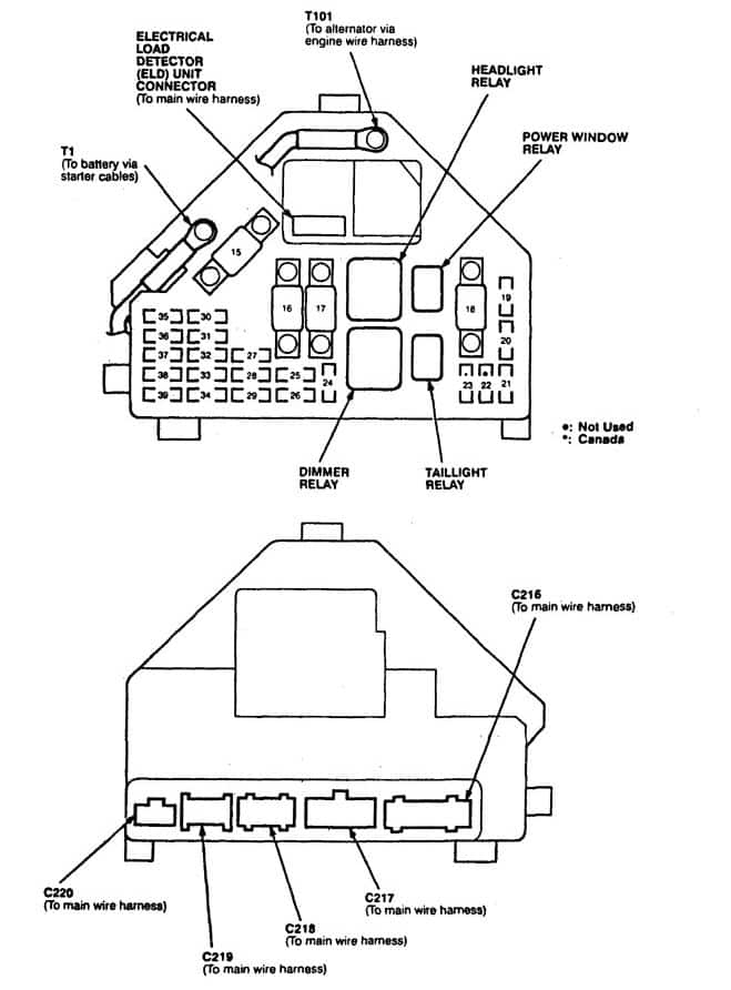
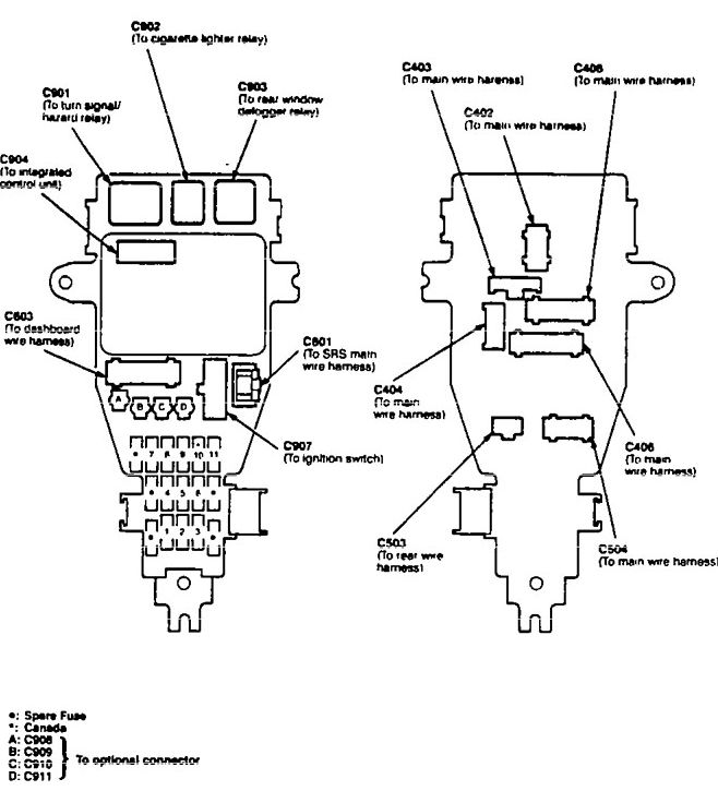
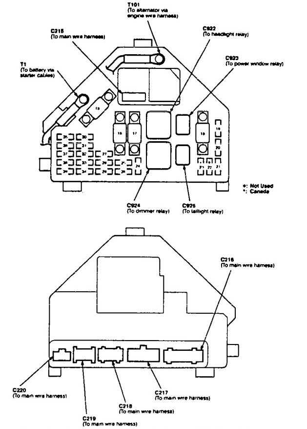
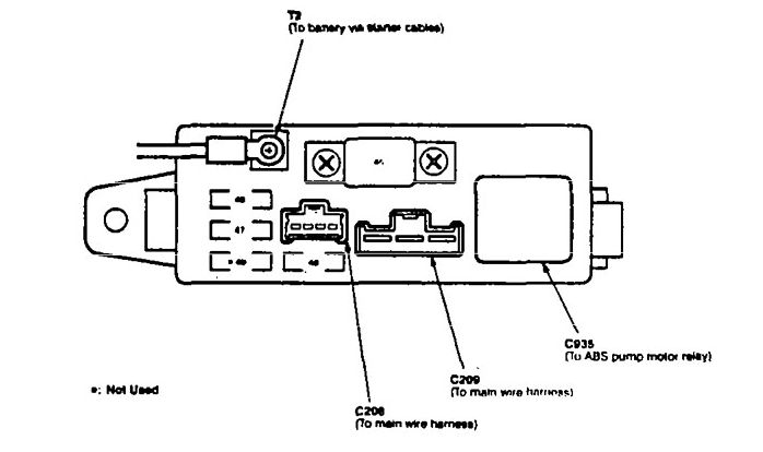
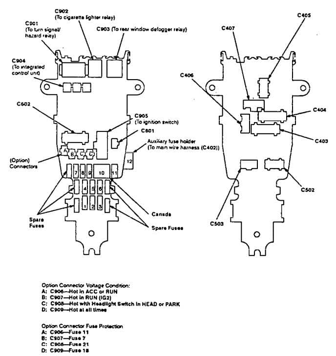
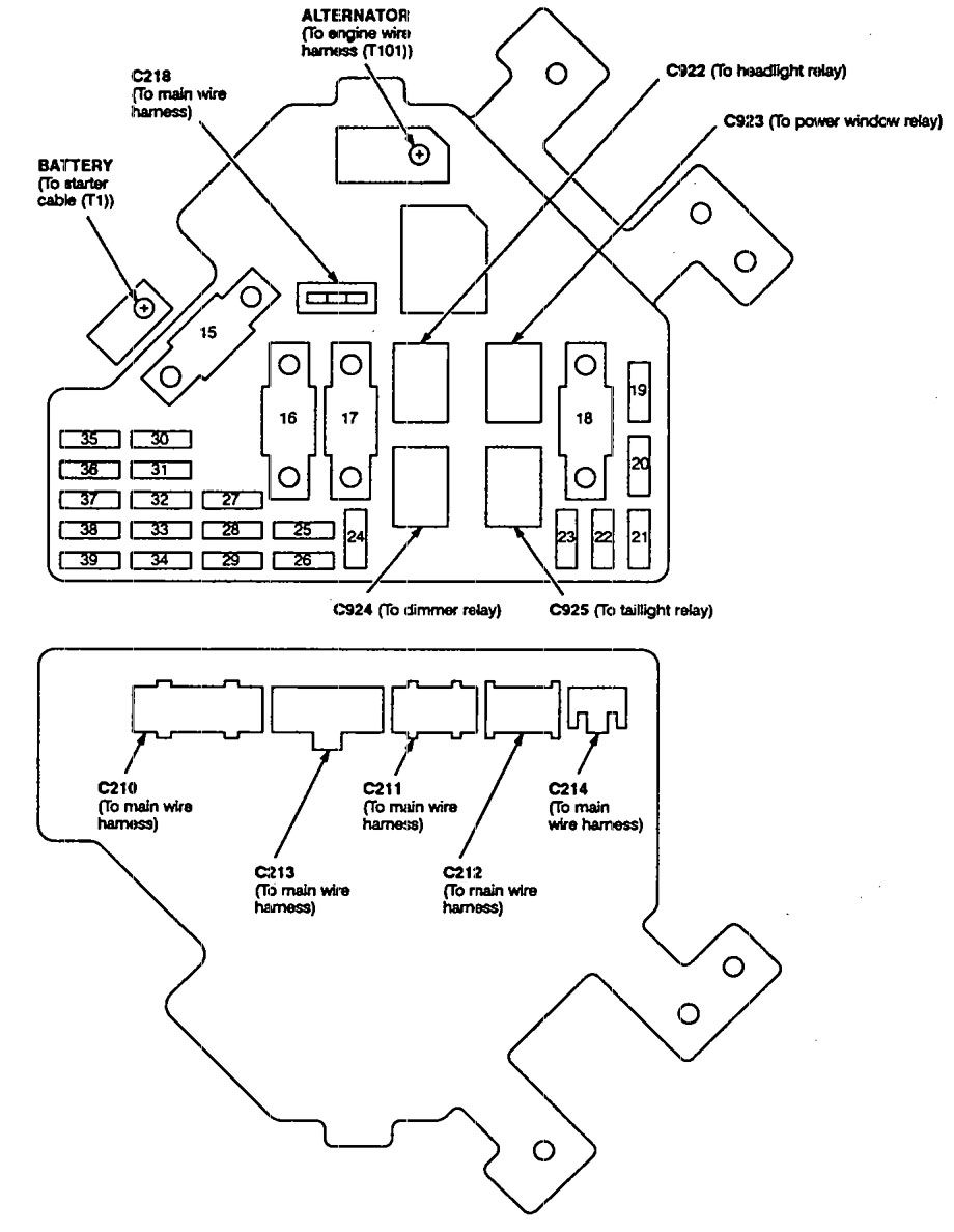
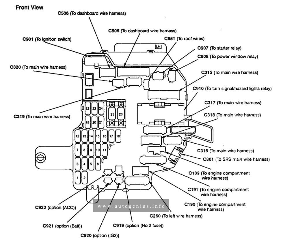
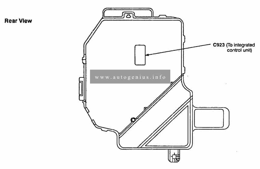
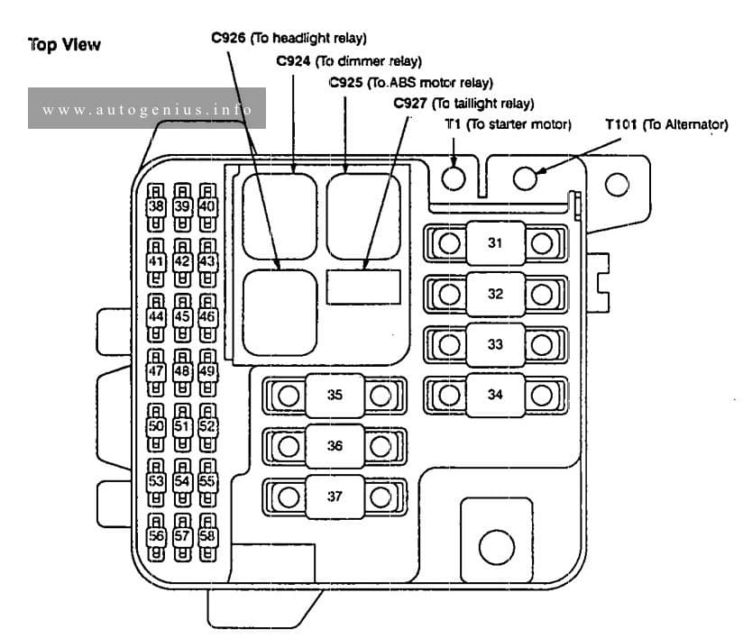
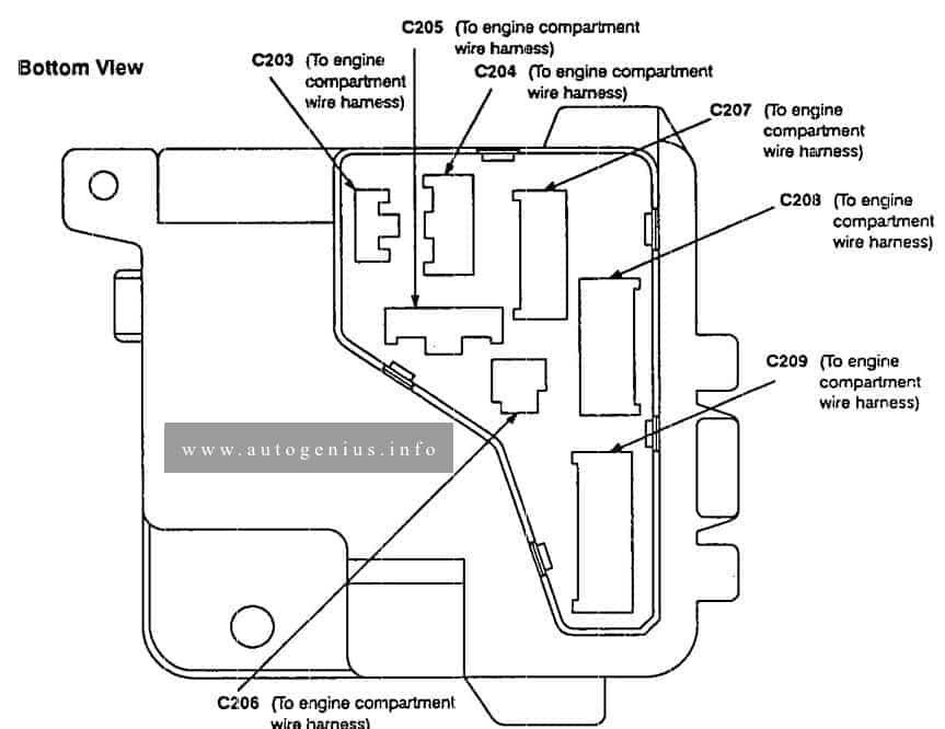
Engine compartment fuse/relay box
Acura TL – fuse box diagram – engine compartment
Position
Fuse name
[A]
Protected component
15
BATTERY
100
Alternator, Power Distribution
16
REAR DEFROSTER
40
Rear window defogger
17
HEATER BLOWER
30
Blower Motor
18
IG
50
Ignition switch (BAT)
19
L-HEADLIGHT
15
Left headlight, Daytime running light (Canada)
20
R-HEADL.IGHT
15
Right headlight, High beam indicator light
21
SMALL LIGHT
15
Dash lights, Parking lights, Security system
22
—
—
—
23
RUNNING LIGHT
15
Daytime running lights control unit (Canada)
24
POWER WINDOW
20
Right rear power window motor
25
POWER WINDOW
20
Left rear power window motor
26
POWER WINDOW FR-R
20
Front passenger’s power window motor
27
POWER SEAT (RECUNING)
20
Driver·s power seat reciline motor, Driver’s power seat rear up-down motor
28
POWER WINDOW FR-L
20
Driver’s power seat recline motor, Power window control unit
29
SUNROOF
30
Moonroof “motor
30
STOP, HORN
20
Horns, Brake lights, Security control unit Interlock system, Ignition key motor
31
POWER SEAT SLIDE
20
Driver’s power seat slide motor, driver’s power seat front up-down motor
32
DOOR LOCK
20
Power door lock control unit
33
ECU
15
PGM-FI main relay
34
CONDENSER FAN
20
Condenser fan motor, A/C compressor clutch
35
HAZARD
10
Hazard warning lights, Turn signal/hazard relay
36
FRONT FOG LIGHT
15
Front log lights
37
INTERIOR LIGHT
15
Ceiling lights, Cigarette lighter, Spotlight, Courtesy lights, Trunk light, Stereo radio/cassette player, Power mirror defogger, Integrated control unit
38
COOLING FAN
15
Radiator fan motor
39
BACK UP, RADIO
10
Engine controle module (ECM), Transmission control module (TCM), Clock, Radiator fan control module, Stereo radio/cassette player, Data link connector (DLC), Climate control unit
Back-up lights, Gauge assambly, Clock, Vehicle speed sesnsor (VSS), Shift lock solenoid, Integrated control unit, Moonroof open relay, Moonroof close relay
2
FUEL PUMP
15
PGM·FI main relay, SRS unit
3
SRS
10
SRS unit
4
ECU, CRUISE CONTROL, EAT ECU
15
Cruise control system, Transmission control module (TCM), Security control unit, Radiator fan control module, Alternator, PGM-FI, ELD unit
5
TURN SIGNAL
7,5
Turn signal/hazard relay
6
WIPER WASHER
30
Windshield wiper motor
7
HEATER, CONTROL RELAY
7,5
Climate control unit, Mode control motor, Recirucation control module, Blower motor relay, Blower motor high relay, Water valve control solenoid valve, Option connector (C909)
Power mirrors, A/C compressor clutch, Radiator fan control module, Rear window defogger relay, Integrated control unit
9
STARTER SIGNAL
7,5
Engine control module (ECM), Gauge assembly, PGM-FI main relay
10
(DAY LIGHTS)
7,5
Daytime running lights control unit (Canada)
11
RADIO
10
Cigarette lighter relay, Option connector (C908)
Engine compartment fuse/relay box
Acura TL – fuse box diagram – engine compartment
Position
Fuse name
[A]
Protected component
15
BATTERY
100
Alternator, Power Distribution
16
REAR DEFROSTER
40
Rear window defogger
17
HEATER BLOWER
30
Blower Motor
18
IG
50
Ignition switch (BAT)
19
L-HEADLIGHT
15
Left headlight, Daytime running light (Canada)
20
R-HEADL.IGHT
15
Right headlight, High beam indicator light
21
SMALL LIGHT
15
Dash lights, Parking lights, Security system
22
—
—
—
23
RUNNING LIGHT
15
Daytime running lights control unit (Canada)
24
POWER WINDOW
20
Right rear power window motor
25
POWER WINDOW
20
Left rear power window motor
26
POWER WINDOW FR-R
20
Front passenger’s power window motor
27
POWER SEAT (RECUNING)
20
Driver·s power seat reciline motor, Driver’s power seat rear up-down motor
28
POWER WINDOW FR-L
20
Driver’s power seat recline motor, Power window control unit
29
SUNROOF
30
Moonroof “motor
30
STOP, HORN
20
Horns, Brake lights, Security control unit Interlock system, Ignition key motor
31
POWER SEAT SLIDE
20
Driver’s power seat slide motor, driver’s power seat front up-down motor
32
DOOR LOCK
20
Power door lock control unit
33
ECU
15
PGM-FI main relay
34
CONDENSER FAN
20
Condenser fan motor, A/C compressor clutch
35
HAZARD
10
Hazard warning lights, Turn signal/hazard relay
36
FRONT FOG LIGHT
15
Front log lights
37
INTERIOR LIGHT
15
Ceiling lights, Cigarette lighter, Spotlight, Courtesy lights, Trunk light, Stereo radio/cassette player, Power mirror defogger, Integrated control unit
38
COOLING FAN
15
Radiator fan motor
39
BACK UP, RADIO
10
Engine controle module (ECM), Transmission control module (TCM), Clock, Radiator fan control module, Stereo radio/cassette player, Data link connector (DLC), Climate control unit
Back-up lights. Gauge assembly, Clock, Vehicle speed sensor (VSS), Integrated control unit
2
15
Emission conttol box, PGM·FI main relay, EVAP purge conttol solenoid valve, Alternator, Radiator fan control module,c Intake air bypass (lAB) control solenoid valve, SRS conltol unit, Gauges, Electric load detector (ELD) unit
3
10
SRS control unit
4
7,5
Cruise control system, Transmission control module (TCM), Security control unit
5
10
Moomoof open relay, Moonroof close relay, Windshield wiper system, Shift lock solenoid (A/T)
6
30
Windshield wipers motor
7
7,5
Heater control amplifter, Heater control panel, Blower motor relay, Blower motor high relay, ABS control unit, ABS tail-saferelays, ABS motor relay, Option B (IG2) connector, ASS inspection connactor
8
7,5
Power mirrors, Power mirror defoggee relay (Canada), A/C compressor clutch, A/C compressor clutch relay, Radiator fan control module, Heated seats (Canada)
9
7,5
ECM. Gauge assembly
10
7,5
Daytime running lights control unit (Canada)
11
10
Stereo radio/cassette player, Audio power amplifier unit, Option A (ACC) connector, Cigarette lighter relay, Cellular phone
This article covers Acura Legend, produced from 1986 to 1995. It includes fuse box diagrams for the 1994 and 1995 models, provides details on the location of the fuse panels inside the vehicle, and explains the function and layout of each fuse.
Passenger compartment
Fuse box location
Under-dash fuse box is located behind left kick panel
Assignment of the fuses in the passenger compartment
Number
A
Component or Citcuit Protected
1
—
Option connector: C921
2
—
Option connector: C919
3
15
ASS pump motor relay, ABS control unit, ABS front and rear failsale relays, ABS inspection connector, A/C compressor clutch, A/C compressor clutch relay, Fan control unit, Radiator fan relay, Rear window defogger relay, Rear window defogger indicator fight, (option C920)
Seat belt presenter, Power door closer control unit
9
15
Cigarette lighter
10
15
Heated seat (seat backs, cushions. and switches)
11
20
A/C compressor clutch relay
12
7,5
Daytime running lights control unit
13
7,5
Integrated control unit, Clock, Gauges, Back-up lights, Turn signal/hazard relay, Shift lock solenoid, Seat belt tension control
14
7,5
Powertrein or engine control module, PGM-FI main relay, Gauge assembly (bulb check circuit)
15
7,5
Powertraln or engine control module, Radiator fan control module, Security control unit, Driving position memory system (OPMS), Charging system
16
20
Daytime running lights control unit
17
20
Power window control unit
18
20
Passenger’s power window motor
19
7,5
Climate control unit, Heater control panel, Seat heater relay, Healed minors, Recirculation control motor, Blower motor relay, Blower motor high relay, Power mirror actuators, Mode control motor (manual A/C)
20
7,5
Cruise control unit. Radiator fan control module, Security control unit, Driving position memory system (DPMS)
21
—
—
22
20
PGM·FI, SRS unit, Charging system, Traction control system (TCS), Vehicle speed sensor (VSS)
Hom relay, Left and right horns, Key Interlock solenoid, Security Indicator, ABS control unit, Cruise control unit, Powetrain or engine control module, Brake lights, Trailer fighting connector
40
15
Tum signal/hazard relay, Hazard warning lights
41
15
ABS control unit (B1)
42
15
ABS control unit (B2), TCS control unit
43
15
ABS control unit (B3)
44
20
Power door lock, control unit, Trunk opener solenoid
45
20
Right headnght. Daytime running lights control unit (Canada)
46
20
Left headlight, High beam indicator light, Daytime running lights control(Canada)
47
20
Radiator fan motor
48
10
Left taillight, Trailer lighting connector
49
15
Front parldng lights, Vanity mirror lights, License plate lights, Right taillights, Integrated control unit, Rear spot lights, Gauge lights, Stereo radio/cassette player, Courtesy light controller (LS and GS), Dash lights brightness control unit, Dash lights
50
20
Condenser fan motor
51
30
Moonroof motor
52
30
Front passenger’s power seat motors (slide-recline)
53
15
Traction control system (TCS)
54
20
Amplifier
55
30
Power seat control unit
56
7,5
Climate control unit, Clock, Stereo radio/cassette player, Power antenna motor, car telephone system, Integrated control unit
57
15
Front courtesy lights, Rear courtesy lights, Trunk light, Footwell lights, Ignition key light, Front and rear celing lights, Trailer lighting connector, Ceiling light relay, Front spot lights
58
30
Steering oolurnn control unit
Fuse box diagram
Acura Legend (1994 – 1995)- fuse and relay box diagram
WARNING: Terminal and harness assignments for individual connectors will vary depending on vehicle equipment level, model, and market.
This article covers Acura Legend, produced from 1986 to 1995. It includes fuse box diagrams for the 1993 models, provides details on the location of the fuse panels inside the vehicle, and explains the function and layout of each fuse.
Passenger compartment
Fuse box location
Under-dash fuse box is located behind left kick panel
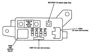
ABS pump motor, No. 38 (7.5 A) fuse, ABS control unit
33
40
YEL/GRN
Rear window defogger, Noise condenser
34
50
WHT/BLK
Under-dash fuse/relay box (BAT)
35
50
WHT
Ignition switch (BAT)
36
40
WHT/GRN
No. 17, 18, 2 f and 24 (20 A) fuses
37
40
BLU/WHT
Blower motor
38
7,5
WHT/BLU
ABS control unit
39
20
WHT/GRN
Brake lights, Horns, Key interlock solenoid (A/T), Security indicator, ABS control unit, Cruise control unit, ECM (M/T) or PCM (A/T), TCS control unit (LS)
40
15
WHT/YEL
Hatard warning tights, Turn signal/hazard relay
41
15
WHT/GRN
ABS. control unit (B1)
42
15
WHT
ABS control unit (B2) ,TCS control unit (LS)
43
15
WHT/BLK
ABS control unit (B3)
44
20
WHT/GRN
Power door lock, control unit, Trunk opener solenoid
45
20
RED/GRN
Right headnght. Daytime running lights control ;unit (Canada)
46
20
RED/YEL
Left headlight, Daytime running lights control unit (Canada)
47
20
WHT
Radiator fan motor
48
10
RED/YEL
Left taitlight, Left rear parking light
49
15
RED/BLK
Right taillight. Front parking lights, Vanity mirror lights, Licensa plate lights, Integrated control unit, Right rear parking light, Dash lights brightness control unit, Dash lights
50
20
WHT
Condenser fan motor
51
30
GRN/WHT
Moonroof motor
52
30
WHT/RED
Passenger’ s. power seat slide and recline motor
52
15
GRN/RED
TCS control unit (LS)
54
20
WHT/BLU
Amplifier (LS)
55
30
RED/WHT
Power seat control unit
56
7,5
WHT/YEL
Stereo radio/cassette player, Clock, Power antenna motor, Climate control unit, Integrated Control unit, Cellular phone system (Option)
57
15
WHT/BLU
Ceiling lights, Courtesy fights, Trunk tight, Foot well lights, lgnition key light, Spot lights. Driver’s door key cylinder light
58
30
WHT/RED
Power seat control unit
Fuse box diagram
Acura Legend (1993)- fuse and relay box diagram
WARNING: Terminal and harness assignments for individual connectors will vary depending on vehicle equipment level, model, and market.
This article covers Acura Legend, produced from 1986 to 1995. It includes fuse box diagrams for the 1992 models, provides details on the location of the fuse panels inside the vehicle, and explains the function and layout of each fuse.
Passenger compartment
Fuse box location
Under-dash fuse box is located behind left kick panel
PGM-FI main relay, electronic air control valve (EACV) solmold, fuel injector resistors
6
—
—
7
20
SRS control unit
8
—
—
9
15
Cigarette lighter
10
15
Heated seat relay
11
—
—
12
7,5
Daytime running lights unit
13
7,5
Integrated control unit, clock; gauges (indicator warning) back up lights, turn signal/hazard lights relay, shift lock solenoid
14
7,5
PGM-Fl/AT electronic control unit, PGM-FI main relay, gauge assembly (bulb check circuit)
15
7,5
Voltage regulator, PGM-FI electronic control unit, fan timer unit, security control unit, ppwer seat control unit
16
20
Daytime running light control unit
17
20
Driver’s power window motor
18
20
Right front power window motor
19
7,5
Climate control unit, NC control unit, heated seat relay, healed mirrors, recirculation control motor. blower relay, high blower relay
20
7,5
Cruise control unit, fan timer unit, security control unit, power seat control unit
21
20
Left rear power window motor
22
20
SRS control unit, PGM-FI main relay, charge light, voltage regulator, vehicle speed sensor, oxygen sensors, bypass control solenoid valves, purge control solenoid valve, PGM-FI/AT eleclronic control unit
Hom relay, left and right hams, key Interlock solenoid, security lnclicator, anti-lock brake control unit, cruise control unit, PGM-FI/AT electronic control unit, brake lights, trailer llgtlting connector
40
15
Under-hood tuse/re1lay box, hazard lights
41
15
Anti-lock brake control unit (B1)
42
15
Anti-lock brake control unit (B2)
43
15
Anti-lock brake control unit (B3)
44
20
Power door lock ccmtrol unit, trunk release solenoid
45
20
Right headlight, daytime running lights unit (Canada)
46
20
Lett headlight, high beam indicator light, daytime running lights unit (Canacla)
47
20
Radiator fan motor
48
10
Lett rem taillight, trailer connector
49
15
Front marker lights, vanity mirror lights, license plate lights, right taillights, integrated control unit, rear dome light, gauge lights, stereo radio/cassette player, courtesy light brightness controller (LS), dashlight brightness controller
50
20
Condenser ran motor
51
30
Sunroof motor
52
30
Right front power seat motors
52
—
—
54
20
Amplifier
55
30
Power seat control unit
56
7,5
Climate control unit, clock, stereo radio/cassette player, power antenna motor, car telephone system, under-dash fuse/relay box
57
15
Front courtesy lights, rear courtesy lights, trunk light, foot lights, Ignition key light, front and rear dome lights, trailer lighting connector, dome light relay
58
30
Power seat control unit
Fuse box diagram
Acura Legend (1992)- fuse and relay box diagram
WARNING: Terminal and harness assignments for individual connectors will vary depending on vehicle equipment level, model, and market.
This article covers Acura Legend, produced from 1986 to 1995. It includes fuse box diagrams for the 1991 models, provides details on the location of the fuse panels inside the vehicle, and explains the function and layout of each fuse.
Passenger compartment
Fuse box locarion
Under-dash fuse box is located behind left kick panel
This article covers Acura Legend, produced from 1986 to 1995. It includes fuse box diagrams for the 1990 models, provides details on the location of the fuse panels inside the vehicle, and explains the function and layout of each fuse.
Assignment of the fuses in the passenger compartment
Fuse number
A
Circuit protected
1
7,5
Power antenna; integrated control unit; radio; climate control; clock; information center control unit
2
20
Power windows (right rear)
3
20
Power windows (right front)
4
20
Power windows (left rear)
5
7,5
Backup lights; integrated.control unit; shift position indicator; clock; gauges: indicators; safety indicator; Information center control unit; turn signal and hazard lights; SRS; shift position, console switch
6
20
Sunroof; wiper/washer motors
7
20
Power door lock control unit; trunk release
8
20
Trailer connector; lights: trunk, ignition key switch, footwall, interior, map, door courtesy, door key; cigarette lighter and illumination