This article covers the first-generation Eagle Talon produced from 1989 to 1998. It includes fuse box diagrams for the 1991 models, provides details on the location of the fuse panels inside the vehicle, and explains the function and layout of each fuse.
Fuse box diagram
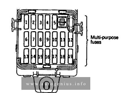
Eagel Talon (1G; 1990) – fuse and relay box diagram
Assignment of the fuses in the fuse box
Power supply circuit
No.
A
Load circuit
Battery
1
10
Automatic seatbelt control unit, key reminder switch, passing control relay, seatbelt warning buzzer, utillight relay
Ignition switch
IG2
2
—
—
3
10
Air conditioner contlol unit, air conditioner switch, defogger timer, heater relay, power window relay, transistor relay*, daytime running light relay 2*, ABS relay
ACC
4
10
Radio
5
15
Cigarette lighter, remote controlled mirror
Battery
6
15
Door lock relay, door lock control unit
Ignition switch
IG2
7
10
4-speed automatic transaxle control unit, auto-cruise control unit <A/T>, combination meter
8
—
—
ACC
9
15
Intermittent wiper relay, wiper motor, washer motor
10
10
Headlight relay, horn, theft-alarm control unit, daytime running high relay 1*
IG1
11
10
Auto-cruise control unit, auto-cruise control actuator automatic seatbelt contyrol unit, combination meter, theft-alarm control unit, seatbelt timer*
12
10
Tum-signal and hazard flasher unit
Battery
13
—
—
14
10
Theft-alarm horn relay
15
—
—
16
30
Blower motor
17
15
Stop light
Ignition switch
IG1
18
10
Back-UP light < M/T>, dome light relay
Battery
19
10
4-speed automatic transaxle control unit, dome light, door-ajar warning light, foot light, ignition key illumination light, luggage compartment light, MPI control unit, radio, security light, ABS relay
*: – vehicle for Canada
WARNING: Terminal and harness assignments for individual connectors will vary depending on vehicle equipment level, model, and market.
Year of production: 2010 2011, 2012, 2013, 2014, 2015, 2016
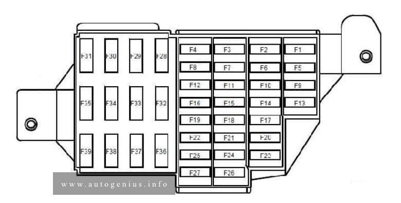
This article covers the first-generation Dacia Duster, produced from 2010 to 2016 It includes fuse box diagrams for the 2010, 2011, 2012, 2013, 2014, 2015 and 2016 models, provides details on the location of the fuse panels inside the vehicle, and explains the function and layout of each fuse.
Driver’s dual rear electric window control – child safety relay control
F14
30
Driver’s dual front electric window control
F15
10
Anti-lock braking system ECU
F16
15
Radio
F17
15
Main electromagnetic horn – secondary electromagnetic horn
F18
10
Rear left-hand side light – front left-hand side light
F19
10
Rear right-hand side light – passenger storage compartment light – instrument panel – UCH – hazard warning lights control – air conditioning control panel – radio – central door locking switch – first row cigarette lighter – 4×4 mode control – right-hand number plate light – left-hand number plate light – front right-hand side light – traction control switch – heated rear screen control – parking proximity sensor switch
F20
7,5
Rear fog light
F21
5
Instrument panel
F22
—
—
F23
15
Fuse on alarm version: Supply to horns via horn relay on board
F24
—
—
F25
—
—
F26
5
Airbag and pretensioner control unit
F27
20
Rear screen wiper motor – wash/wipe combination switch – reversing lights switch – neutral and reversing sensor on manual gearbox – automatic gearbox module – parking proximity sensor electronic control unit
F28
15
Consumer cut-out – instrument panel – radio – UCH
F29
15
UCH – diagnostic socket – anti-theft tracker unit
F30
20
UCH
F31
15
Supply to front right-hand and left-hand fog light via front fog relay on board – instrument panel indicator light
F32
30
heated rear screen switch
F33
—
—
F34
15
Front-rear torque distribution electric control unit
F35
—
—
F36
30
Cold air blower unit supply via cold air blower unit relay and air conditioning control panel
F37
5
Right-hand and left-hand electric door mirror supply via electric door mirror control
F38
15
Radio – first row cigarette lighter
F39
10
Cold air blower unit relay control
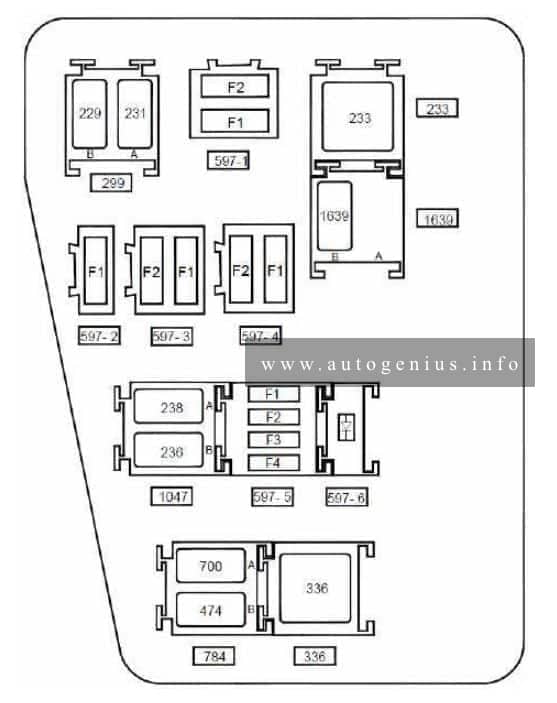
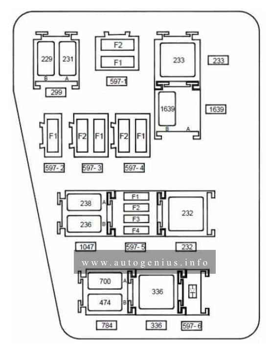
Relay box location
This relay is located in the passenger compartment, in the lower left-hand section of the dashboard
Anti-lock braking system electric control unit on versions without electronic stability program
F2
25
Anti-lock braking system electric control unit on versions without electronic stability program
Fuse board 597- 2
F1
40
Fuse on air conditioning version: Cooling fan assembly supply via fan assembly high-speed relay or via fan assembly low speed relay on relay board and fan assembly resistor – air conditioning clutch supply via air conditioning clutch relay on board
Fuse board 597- 3
F1
60
Ignition switch – monolever – supply to fuse F23 on passenger compartment fuse box
F2
60
Monolever supply – supply to fuses F29 and F36 on passenger compartment fuse box
Fuse board 597- 4
F1
—
—
F2
25
F34 fuse supply on passenger compartment fuse box on 4×4 version (four wheel drive)
Fuse board 597- 5
F1
30
Fuse on standard heating version: cooling fan assembly supply via low speed fan assembly relay on relay board
F2
25
Injection locking relay control and supply on relay board – fuel pump relay supply on relay board
Anti-lock braking system electric control unit on versions without electronic stability program
F2
25
Anti-lock braking system electric control unit on versions without electronic stability program
Fuse board 597- 2
F1
40
Fuse on air conditioning version: cooling fan assembly supply via high speed fan assembly relay or via low speed fan assembly relay on relay board and fan assembly resistor
Fuse board 597- 3
F1
60
Ignition switch – monolever – supply to fuse F23 on passenger compartment fuse box
F2
60
Monolever supply – supply to fuses F29 and F36 on passenger compartment fuse box
Fuse board 597- 4
F1
—
—
F2
25
F34 fuse supply on passenger compartment fuse box on 4×4 version (four wheel drive)
Fuse board 597- 5
F1
15
Fuse on air conditioning version: Air conditioning clutch supply via air conditioning clutch relay on board
F2
25
Injection locking relay control and supply on relay board – fuel pump relay supply on relay board
F3
—
—
F4
15
Automatic gearbox electric control unit (119) with 4-speed automatic gearbox on F4R403 and F4R405 engines
Diode 597- 6 support plate
Diode
Air conditioning clutch
Relay board 299
A
20
Front fog lights
B
20
Horn
Unit relay 233
233
40
Cold air blower
Relay board 1047
A
20
Injection locking
B
20
Fuel pump
Relay board 784
A
20
Low speed fan assembly
B
20
Air conditioning clutch
Unit relay 336
336
40
High speed fan assembly
Unit relay 232 on automatic gearbox version
22
40
Starter
Relay 1639 board on FLEXFUEL version
A
—
—
B
20
Additional fuel pump
WARNING: Terminal and harness assignments for individual connectors will vary depending on vehicle equipment level, model, and market.