Acura CL (3.0/2.2/2.3; 1997 – 1999) – fuse and relay box diagram
Year of productions: 1997, 1998, 1999
This article covers the second-generation Acura CL, produced from 1997 to 2003. It includes fuse box diagrams for the 1997, 1998, and 1999 models, provides details on the location of the fuse panels inside the vehicle, and explains the function and layout of each fuse.
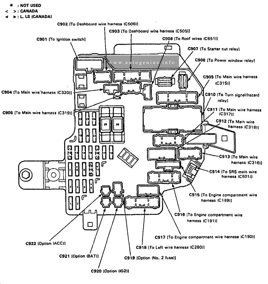
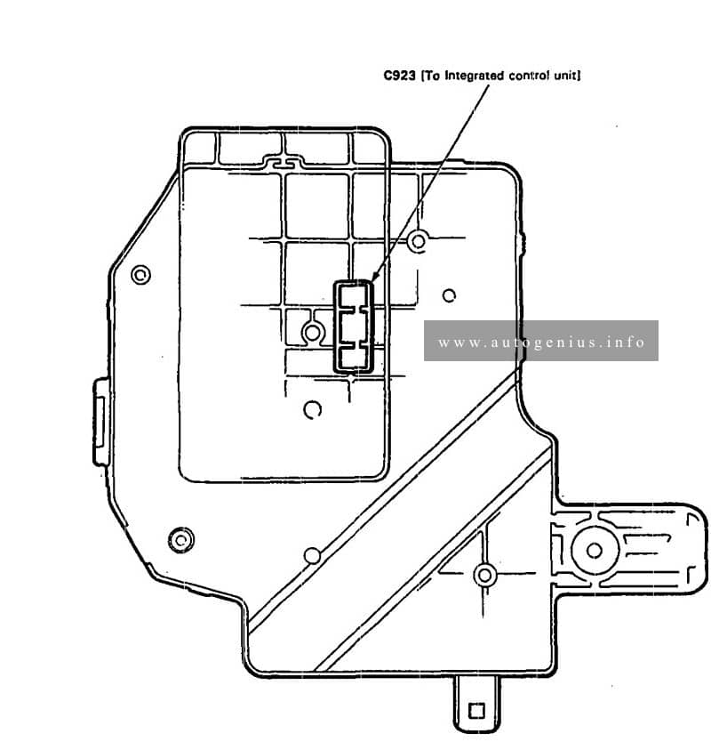
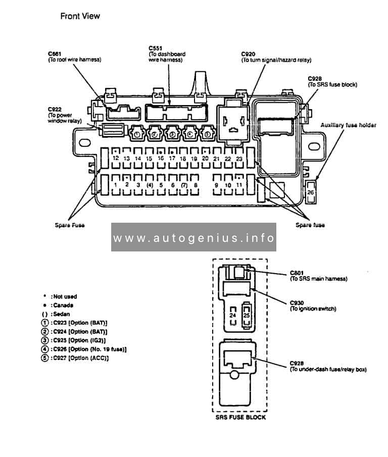
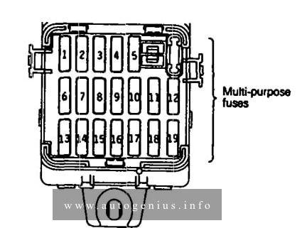
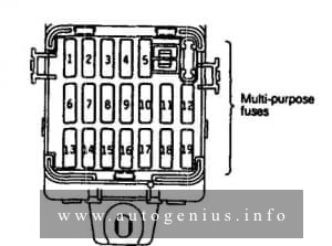
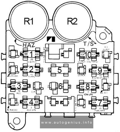
Passenger copmartment
Fuse box diagram
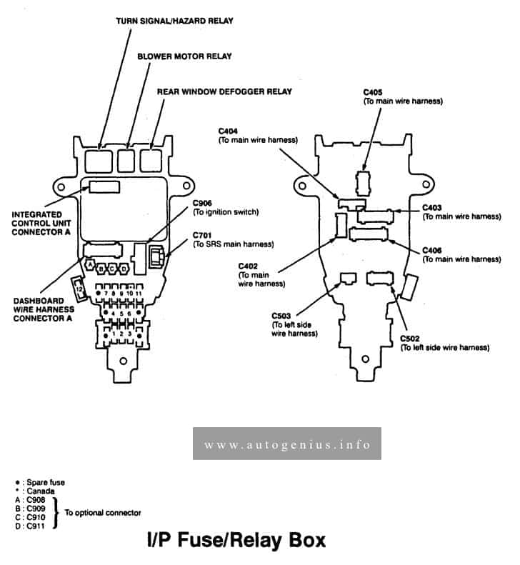
Assignment of the fuses in the passenger compartment
| Fuse number | Fuse name | Ampere rating [A] | Component or circuit protected |
| 1 | BACK·UP LIGHTS, METER LIGHTS, CLOCK, SECURITY | 10 | Gauge assembly, Back-up lights, Clock, Vehicle speed sensor (VSS), Shill loCk solenoid, Integrated control unit, Keyless/security control unit |
| 2 | FUEL PUMP | 15 | PGM·FI main relay, SRS unit |
| 3 | SRS | 10 | SRS unit |
| 4 | ECU, EAT ECU CRUISE CONTROL FAN TIMER | 7,5 | Charging system,Radiator tan control module, Cruise control, PGM·FI, TCM (3.0L) |
| 5 | IGN COIL | 15 | Ignition (3.0L) |
| 6 | WIPER WASHER | 30 | Wiper/washer, Integrated control unit |
| 7 | R/C MIRROR (HEATED MIRROR) HEATED SEAT) | 7,5 | Anti-lock brake system (ABS), Power mirrors, Seat heaters |
| 8 | HEATER CONTROL RELAY, A/C CLUTCH RELAY, COOLING FAN RELAY | 7,5 | Air delivery, A/C compressor controls, Fans, Rear window defogger |
| 9 | STARTER SIGNAL | 7,5 | Gauge assembly, PGM·FI main relay, Powertrain or Engine control module (PCM or ECM), Starter cut relay, A/T gear position switch or Clutch interlock switch |
| 10 | (DAY LIGHTS) | 7,5 | Daytime running lights control unit (Canada) |
| 11 | RADIO AUDIO AMPLIFER | 10 | Cigarette lighter relay, Stereo amplifier (3.0L) |
| 12 | TURN SIGNALS | 7,5 | Turn signal/hazard relay |
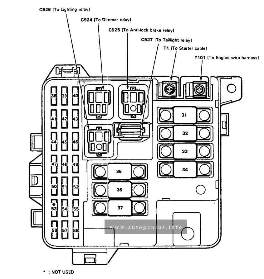
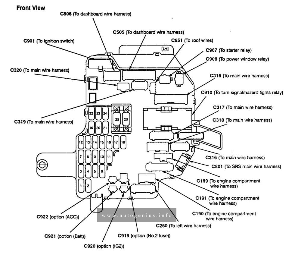
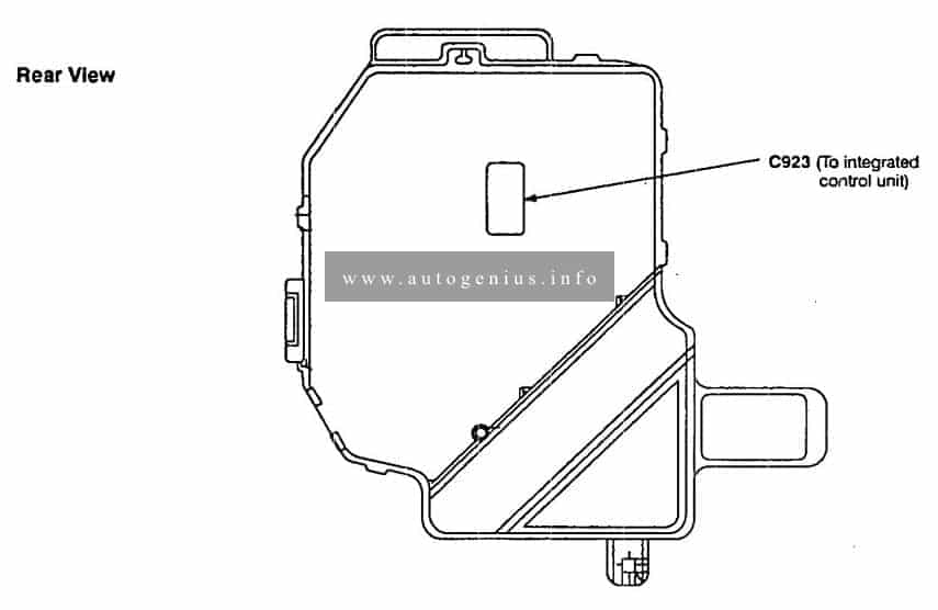
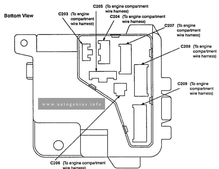
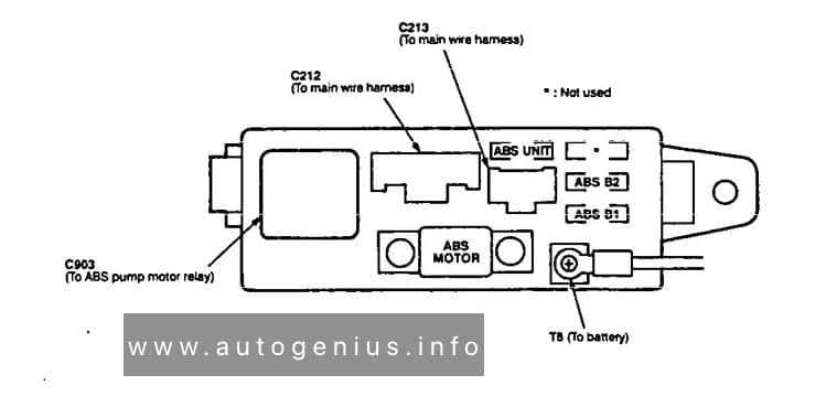
Engine compartment
Fuse box diagram (ABS Fuse/Relay box)
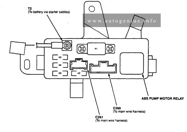
Assignment of the fuses in the engine compartment (ABS fuse/relay box)
| Fuse number | Fuse name | Ampere rating [A] | Component or Circuit protected |
| 41 | ABS MOTOR | 40 | ABS pump motor relay |
| 42 | ABS UNIT | 10 | ABS control unit |
| 43 | ABS B1 | 20 | ABS front fall·safe relay |
| 44 | ABS B2 | 15 | ABS rear fail-safe relay, ABS control unit |
| 45 | — | — | — |
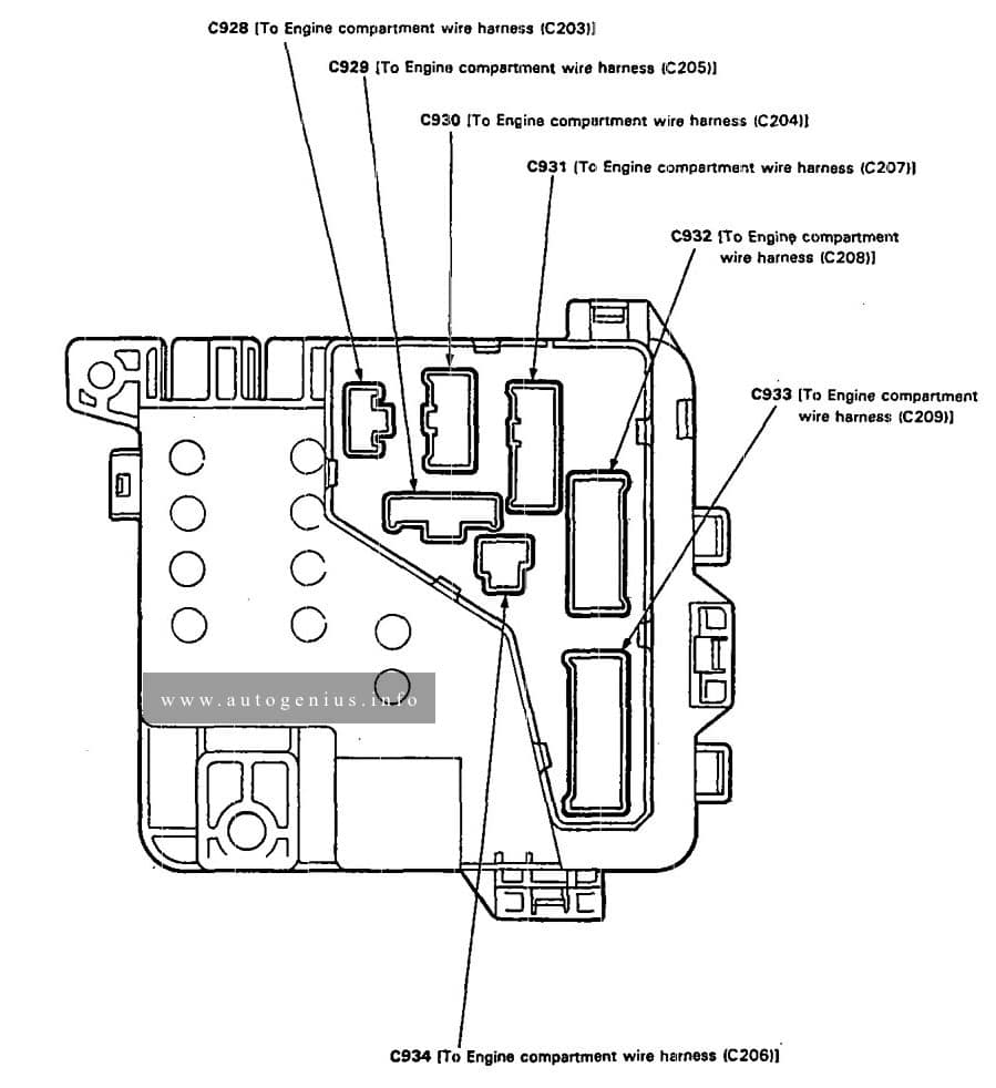
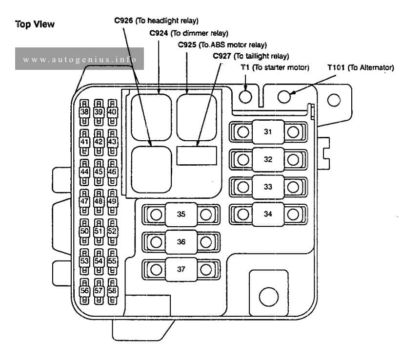
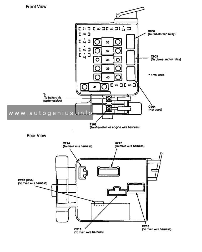
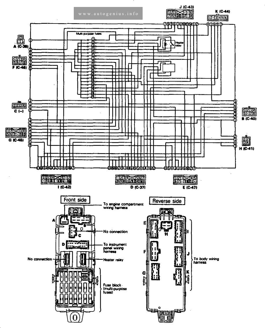
Engine compartment
Fuse box diagram
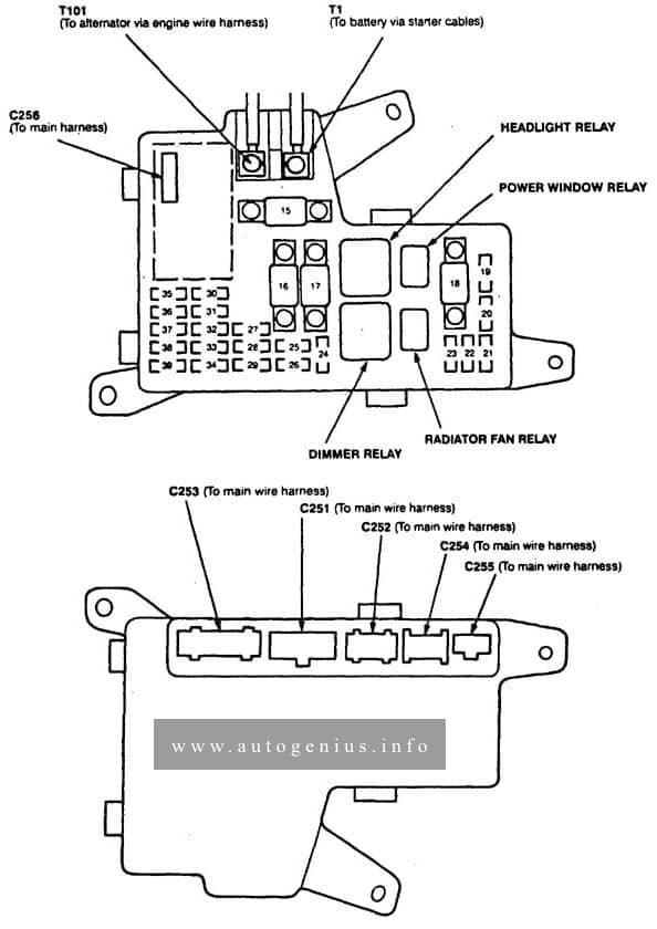
Assignment of the fuses in the engine compartment
| Fuse number | Fuse name | Ampere rating [A] | Component or Circuit protected |
| 15 | BATTERY | 100 | Power distribution |
| 16 | REAR DEFROSTER | 40 | Rear window defogger |
| 17 | HEATER BLOWER | 40 | Blower motor relay |
| 18 | IGN SW | 50 | Ignition switch (BAT) |
| 19 | L-HEADLIGHT | 20 | Left headlight, Daytime running lights control unit (Canada), Hi beam indicator |
| 20 | R-HEADLIGHT | 20 | Right headlight, Daytime running lights control unit (Canada) |
| 21 | COOLING FAN | 20 | Radiator fan relay |
| 22 | (HEATED SEAT) | 15 | Seat heater main relay |
| 23 | RUNNING LIGHT | 10 | Daytime running lights control unit Canada) |
| 24 | — | — | — |
| 25 | — | — | — |
| 26 | POWER WINDOW FR-R | 20 | Passenger’s front power window motor, Moonroof control unit |
| 27 (2.2L) | POWER SEAT | 20 | Driver’s power seat motors |
| 27 (3.0L) | POWER SEAT FR HEIGHT | 15 | Driver’s power seat motors |
| 28 | POWER WINDOW FR-L | 20 | Driver’s power window motor |
| 29 | SUN ROOF | 30 | Moonroof motor |
| 30 | STOP LIGHT HORN | 20 | Horns, Brake lights, Key interlock solenoid (A/T), ABS control unit, Cruise control, PGM-FI, TCM (3.0L A/T) |
| 31 (3.0L) | POWER SEAT RR HEIGHT RECLINE | 20 | Driver’s power seat motors, Power seat control unit |
| 32 | SMALL LIGHT | 15 | Dash lights, Parking lights, Taillights, License plate lights |
| 33 | ECU | 15 (20 2.2L A/T) | PGM-FI main relay |
| 34 | CONDENSER FAN | 15 (20 3.0L) | Radiator control module (3.3L), Condenser fan relay, A/C compressor clutch relay |
| 35 | HAZARD | 15 | Hazard warning switch |
| 36 | RADIO CIGAR LIGHTER | 15 | Cigarette lighter, Audio unit Data link connector (DLC) |
| 37 | INTERIOR LIGHT | 7,5 | Integrated control unit, Trunk light, Courtesy lights, Ceiling light, Sportlights |
| 38 | SECURITY DOOR LOCK | 15 | Keyless/security control unit |
| 39 | BACK-UP (RADIO) (FAN TIMER 3.0L) | 7,5 | Powertrain or Engine control module (PCM or ECM), Clock, Audio unit, Security indicator, TCM (3.0L), Radiator fan control module (3.0L) |
WARNING: Terminal and harness assignments for individual connectors will vary depending on vehicle equipment level, model, and market.