Ford Escort (1990 – 1996) – fuse and relay box diagram (USA version)
Year of production: 1990, 1991, 1992, 1993, 1994, 1995, 1996
This article focuses on the second-generation Ford Escort (North American version), produced from 1991 to 1996. It provides fuse box diagrams for the 1994, 1995, and 1996 models, along with information on the location of the fuse panels inside the vehicle and the function and layout of each fuse and relay.
Passenger compartment fuse box
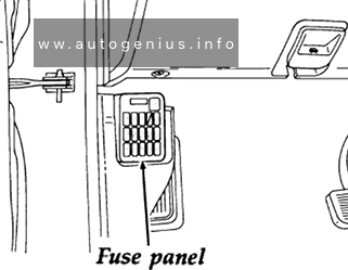
Fuse Box Location
The interior fuse panel is below the instrument panel in front of the driver’s door.
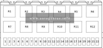
Fuse Box Diagram
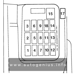
Assignment of the fuses in the passenger compartment
| Fuse/CB | Ampere rating [A] | Description |
| 1 | 10 | A/c on indicator, air conditioner relay, air conditioner switch, daytime running lamp module, daytime running lamp relay, rear wiper and washer motor, wide-open throttle cutout relay |
| 2 | 30 | Door lock motor |
| 3 | 20 | Brakelamp, electronic automatic transaxle module powertrain control module, high-mount brakelamp, horn, shift interlock system, speed control |
| 4 | 15 | Hazard flashers, front and rear turn lamp, turn indicator lamp |
| 5 | 30 | Passive belt control module, passive belt motor |
| 6 | 15 | Powertrain control module (1.8l engine), ecterior lamps, interior illumination, parking lamp relay, warning chime module |
| 7 | 15 (1.8l engine) | Dome and map lamp, door lock switch, engine room, ignition key illumination, luggage lamp, premium sound amplifier, radio (memory), powertrain control module, shift interlock system, visor mirror lamp, warning chime module |
| 15 (1.9l engine) | ||
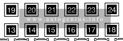
| 8 | 30 | Power window motor |
| 9 | 15 | Moon roof motor |
| 10 | 15 | Cooling fan system, powertrain control module power relay |
| 11 | 15 | Air bag diagnostic module, backup lamps, cluster, flasher unit, passive belt control module, powertrain control module (Canada only), shift-lock system, speed control, turn signal flasher, warning chime |
| 12 | 15 | Instrument panel dimmer module, radio, remote control mirror |
| 13 | 20 | Front wiper and washer motor, interval governor, interval wiper and washer switch |
| 14 | 20 | Powertrain control module (1.8l engine), rear window defrost |
| 15 | 30 circuit breaker | Blower motor, powertrain control module (1.8l engine) |
| 16 | 10 (1.9l engine) | Heated exhaust gas oxygen sensor (1.9l engine) (on joint box side, not shown) |
| 20 (1.8l engine) | Horn (on joint box side, not shown) | |
| 17 | 20 | Cigar lighter (on joint box side) |
| 18 | 10 | Anti-lock brake system (1.8l engine) |
Engine Compartment Fuse Box
Fuse Box Location
The fuse box is under the hood near the battery.
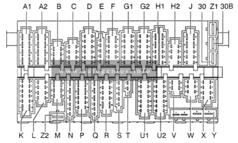
Fuse Box Diagram
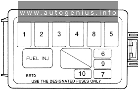
Assignment of the fuses in the engine compartment
| Fuse/CB | Ampere rating [A] | Description |
| 1 | 30 | Changing system (1.8l engine), fuel injection system |
| 2 | 30 FL | Daytime running lamps (Canada), fog lamps, headlamps, high beam indicator |
| 3 | 80 FL (1.8l engine) | Chargine system, engine compartment fuse panel (ABS, A/C, BTN, fan, horn (1.8l engine)), engine controls, instrument cluster (manual transaxle only), intrument panel fuse panel (cigar, defrost, engine ABS, heater, HEGO (1.9l engine), meter power window, radio, rear wiper, sun roof), starting system |
| 100 FL (1.9l engine) | ||
| 4 | 60 FL (1.8l engine) | Charging system (1.9l engine), instrument panel fuse panel (belt, door lock, hazard, room, stop, tail) |
| 40 FL (1.9l engine) | ||
| 5 | 30 (1.8l MTX engine | Cooling fan system |
| 40 (1.9l engine, 1.8l ATX engine) | ||
| 6 | 10 (1.9l engine | Air conditioner magnet clutch, powertrain control module (1.9l engine) |
| 20 (1.8l engine | ||
| 7 | 10 FL (1.8l engine | Fuel pump relay, powertrain control unit module |
| 20 (1.9l engine | Fuel pump | |
| 8 | 60 (1.8l engine | Anti-lock brake system |
| 9 | 10 | Air bag diagnostic module |
| 10 | 20 (1.8l engine) | Fuel pump |
| 10 (1.9l engine) | OBD-II (Data link connector) |
The circuit breaker chart
| Circuit protected | Size | Location |
| Blower motor, PCM module (1.8l engine) | 30 | Power distribution box above fuse panel |
WARNING: Terminal and harness assignments for individual connectors will vary depending on vehicle equipment level, model, and market.