VW Golf 1 (mk1; 1981 – 1984) – fuse and relay box diagram
(U.S – built models with fuel injectors)
Year of production: 1981, 1982, 1983, 1984
The 1st generation Volkswagen Golf compact car was produced (U.S – built) in 1975, 1976, 1977, 1978, 1979, 1980, 1981, 1982, 1983 and 1984 with gasoline and diesel engines. Delivered worldwide in various body styles: convertible, sedan, station wagon and hatchback. In this article you will find a designation of the fuse and relay boxes diagram of the 1st generation Volkswagen Golf.
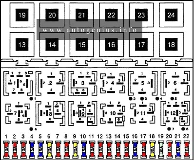
Fuse box diagram
Assignment of the fuses and in the fuse box diagram
| Fuse | Ampere rating [A] | Part Number | Circuit | Power source |
| 1 | 30 | N17131.9 | Radiator fan motor | Terminal 30 — battery |
| 2 | 15 | N17131.6 | Parking lights | Terminal 30 — battery |
| 3 | 20 | N17131.7 | Horn | Terminal 30 — battery |
| 5 | 4 | N17131.2 | Dashboard and console illuminating lights | Headlight switch |
| 6 | 30 | N17131.9 | Fuel pump relay | Terminal 30 — battery |
| 9 | 10 | N17131.5 | Rear window wiper motor | Terminal 15 — ignition switch |
| 10 | 15 | N17131.6 | Turn signal | Terminal 15 — ignition switch |
| 11 | 5 | N17131.3 | Radio | Terminal 15 — ignition switch |
| 12 | 10 | N17131.5 | Back-up lights, cruise control | Terminal 15 — ignition switch |
| 19 | 25 | N17131.8 | Heater motor | Terminal X – load reduction relay |
| 20 | 25 | N17131.8 | Rear window deffoger | Terminal X – load reduction relay |
| 21 | 20 | N17131.7 | Windshield wiper motor | Terminal X – load reduction relay |
| 24 | 15 | N17131.6 | Brake lights and emergency flasher | Terminal 30 — battery |
| 25 | 15 | N17131.6 | Dome, clock and glove compartment lights | Terminal 30 — battery |
| 26 | 10 | N17131.5 | Cigarette lighter | Terminal 30 — battery |
| 27 | 4 | N17131.2 | Horn relay | Terminal 30 — battery |
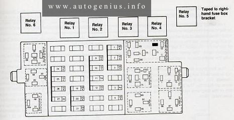
Auxiliary relays
Assignment of the relay and in the fuse box diagram
| Relay number | Model years | Component |
| 1 | 1981 – 1983 | Upshift control |
| 1984 | Fuel pump | |
| 2 | 1981 – 1983 | Rear window wiper/washer |
| 1984 | Oxygen sensor control | |
| 3 | 1981 – 1982 | Hot-start pilse |
| 1983 | Oxygen sensor control | |
| 1984 | Rear window wiper/washer | |
| 4 | 1981 – 1982 | Oxygen sensor control |
| 1984 | Upshift control | |
| 5 | 1983 – 1984 | Hot-start pulse |
| 6 | 1981 – 1983 | Fuel pump |
| 1984 | Oil pressure warrning system |
WARNING: Terminal and harness assignments for individual connectors will vary depending on vehicle equipment level, model, and market.