Mazda Premacy (2001 – 2004) – fuse and relay box diagram
Year of production: 2001, 2002, 2003, 2004
This article covers the first-generation Mazda Premacy (CP), manufactured from 1999 to 2004. It includes fuse box diagrams for the 2001, 2002, 2003, and 2004 models, along with details on the location of the fuse panels inside the vehicle and explanations of each fuse and relay assignment (fuse layout).
Passenger compartment fuse box
Fuse Box Location
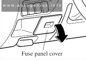
The fuse panel is located behind the cover on the driver’s side.
Fuse Box Diagram
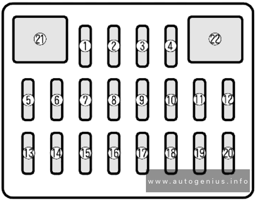
Assignment of the fuses in the instrument panel
| № | Name | Amps | Description |
|---|---|---|---|
| 1 | – | – | – |
| 2 | – | – | – |
| 3 | – | – | – |
| 4 | M/DEF | 7.5A | Mirror defroster, For protection of various circuit |
| 5 | S/W | 15A | Seat warmer, For protection of various circuit |
| 6 | A/C | 15A | Air conditioner, For protection of various circuit |
| 7 | – | – | – |
| 8 | – | – | – |
| 9 | – | – | – |
| 10 | METER | 10A | Instrument cluster |
| 11 | ENG | 10A | Engine control system |
| 12 | R.WIP | 10A | Rear window wiper and washer |
| 13 | RADIO | 15A | Audio system, For protection of various circuit |
| 14 | OPT | 15A | Accessory socket |
| 15 | H/CLN | 20A | Headlight cleaner, For protection of various circuit |
| 16 | ST.SIG | 7.5A | Engine control system |
| 17 | – | – | – |
| 18 | P/W | 30A | Power windows, For protection of various circuit |
| 19 | D/L | 30A | Power door locks, For protection of various circuit |
| 20 | ROOM | 10A | Interior lights, Liftgate light |
| 21 | WIPER | 20A | Windscreen wiper and washer |
| 22 | P/W | 30A | Power windows, For protection of various circuit |
Engine compartment fuse box
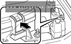
Fuse Box Location
Fuse Box Diagram
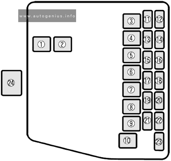
Assignment of the fuses in the engine compartment
| № | Name | Amps | Description |
|---|---|---|---|
| 1 | HEATER | 40A | Heater |
| 2 | ABS | 60A | Antilock brake system |
| 3 | IG KEY 1 | 40A | For protection of various circuits |
| 4 | PTC | 30A | PTC heater |
| 5 | GLOW | 40A | Glow plug |
| 6 | IG KEY 2 | 40A | For protection of various circuits |
| 7 | COOLING FAN | 30A | Cooling fan |
| 8 | BTN | 40A | Interior lights, Power door locks |
| 9 | AD FAN | 30A | Additional cooling fan for air conditioner, For protection of various circuits |
| 10 | INJ OR FIP | 30A | Engine control system |
| 11 | A/C | 10A | Air conditioner, For protection of various circuits |
| 12 | – | – | – |
| 13 | HORN | 10A | Horn |
| 14 | HAZARD | 10A | Hazard warning flashers |
| 15 | TAIL | 15A | Tail lights, Parking light, Number plate light, Illumination |
| 16 | HEAD C/U | 10A | For protection of various circuits |
| 17 | FOG | 15A | – |
| 18 | F.FOG & DEISER | 15A | Front fog light |
| 19 | STOP | 15A | Brake lights |
| 20 | HEAD-R | 15A | Headlight (right) |
| 21 | HEAD-L | 15A | Headlight (left) |
| 22 | – | – | – |
| 23 | HEAD HI | 7.5A | – |
| 24 | MAIN | 100A | For protection of ALL circuits |
WARNING: Terminal and harness assignments for individual connectors will vary depending on vehicle equipment level, model, and market.