Volkswagen Polo (6N/6KV; 1999 – 2002) – fuse and relay box diagram
Year od production: 1999, 2000, 2001, 2002
This article covers the third-generation Volkswagen Polo (Typ 6N/6KV), manufactured between 1994 and 2002. It includes fuse box diagrams for the 1999 through 2002 models, details the locations of the fuse panels within the vehicle, and provides information on the fuse and relay assignments (fuse layout)
Passenger Compartment
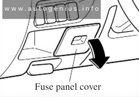
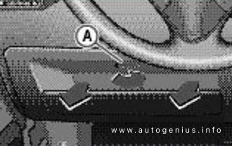
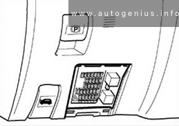
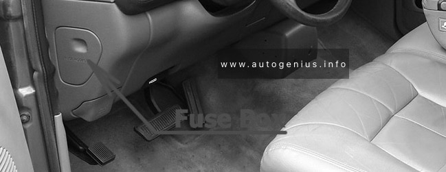
Fuse box location
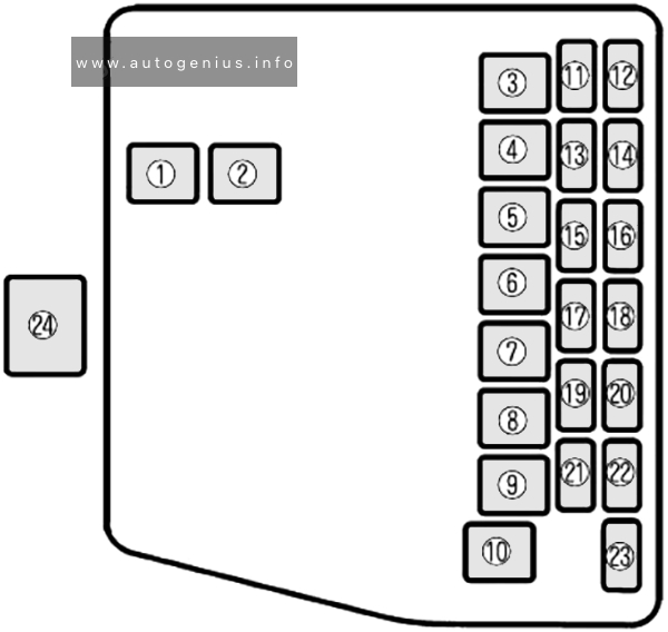
The fuse box is located behind the cover in driver’s storage compartment.
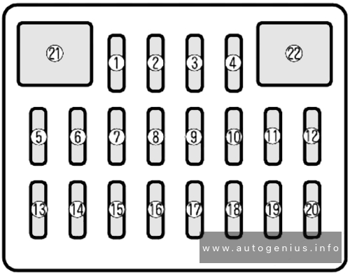
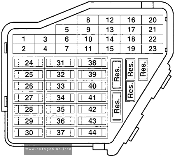
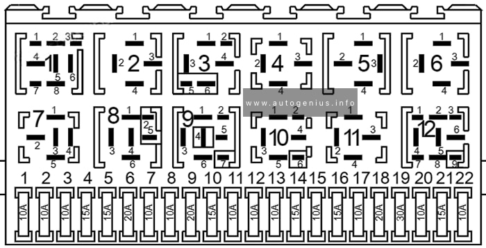
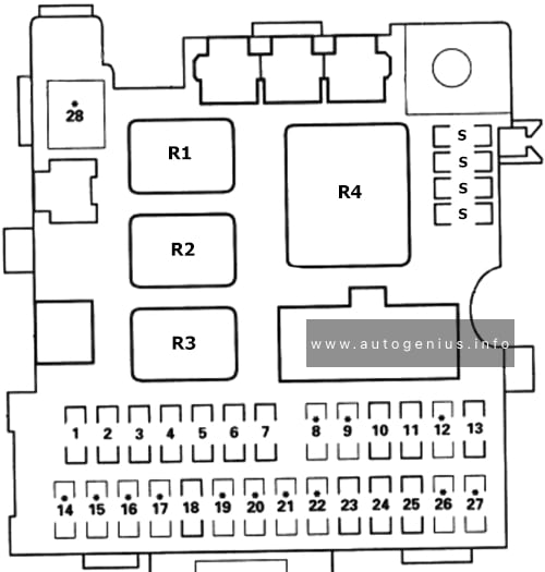
Fuse box diagram
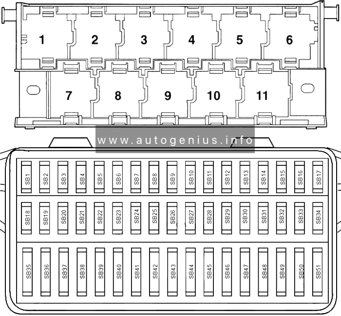
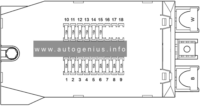
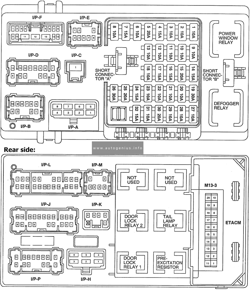
Assignment of the fuses in the instrument panel
| № | Amps | Description |
|---|---|---|
| SB1 | 10A | Lambda probe heating, ACF; camshaft variable timing adjuster |
| SB2 | 5A | Number plate lights |
| SB3 | 10A | Injectors |
| SB4 | 5A | Side bulb left |
| SB5 | 5A | Side light bulb |
| SB6 | 15A | Rear wiper |
| SB7 | 75A | Turn signals |
| SB8 | 5A | ABS with EDL/ESP |
| SB9 | 5A | Headlight range control |
| SB10 | 7.5A | Interior lighting, glove box, mirror, door entry, luggage compartment light |
| SB11 | 5A | Self-diagnosis connection voltage supply, dash panel insert, Climatronic |
| SB12 | 10A | Right headlight main beam, main beam warning lamp |
| SB13 | 10A | Left main beam headlight |
| SB14 | 10A | Hazard warning lights system, anti-theft alarm system |
| SB15 | 10A | Brake lights |
| SB16 | 5A | Ignition/starter switch S-contact |
| SB17 | – | – |
| SB18 | 5A | Mirror heating |
| SB19 | 15A | Horn |
| SB20 | 10A | Telephone/preparationfor telephone |
| SB21 | 5A | Automatic gearbox control unit |
| SB22 | 15A | Anti-theft alarm system horn |
| SB23 | 5A | EGR, air mass meter, addit. heater relay, glow plug relay |
| SB24 | 5A | Clutch pedal switch (diesel), brake light suppression switch (EPC) |
| SB25 | 5A | Selector lever switch (AG4) |
| SB26 | 7.5A | Air conditioner, central locking, electric windows, electric mirrors, navigation |
| SB27 | 5A | Dash panel insert |
| SB28 | 5A | Speedometer sender, immobilizer |
| SB29 | 75A | Reversing lights, washer jet heating, headlight range control motor |
| SB30 | 5A | Exhaust gas recirculation valve, activated charcoal filter solenoid, heater pipe |
| SB31 | 5A | Fuel shut-off control unit, engine control unit |
| SB32 | 5A | Fuel shut-off control unit (diesel) |
| SB33 | 10A | Automatic gearbox selector lever lock |
| SB34 | 10A | Ignition transformer |
| SB35 | 25A | Glass sunroof, fabric sunroof |
| SB36 | 15A | Engine control unit |
| SB37 | 15A | Engine control unit |
| SB38 | 25A | Driver’s door power window |
| SB39 | 25A | Front passenger’s power window |
| SB40 | 15A | Fuel pump |
| SB41 | 15A | Central locking, anti-theft alarm system |
| SB42 | 15A | Radio, navigation |
| SB43 | 15A | Fog light, rear fog light |
| SB44 | 15A | Dipped beam, left headlight |
| SB45 | 15A | Dipped beam right headlight |
| SB46 | 15A | Cigarette lighter |
| SB47 | 20A | Headlight washer system |
| SB48 | 20A | Heated rear window |
| SB49 | 25A | Fresh air blower |
| SB50 | 15A | Windscreen wiper system, windscreen washer pump |
| SB51 | 15A | Seat heating |
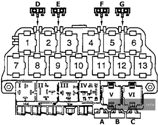
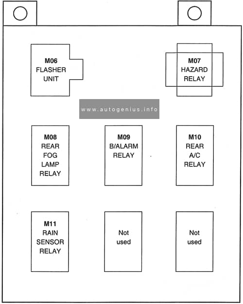
| Relays: | ||
| 1 | Fuel pump relay (petrol engines only) Fuel shut-off control unit (diesel engines) |
|
| 2 | Automatic intermittent wash/wipe and rain sensor relay | |
| 7 | X contact relief relay | |
| 8 | Heated exterior mirror relay |
Engine Compartment
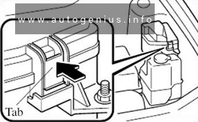
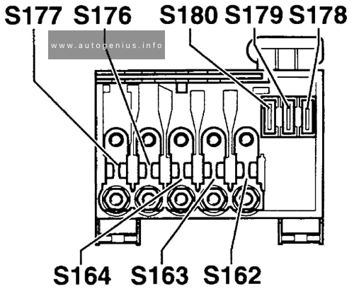
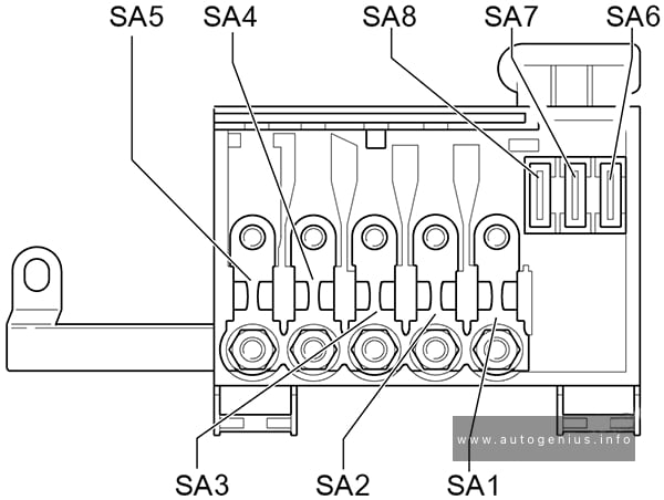
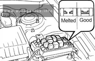
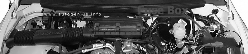
Fuse box location
It is located on the battery.
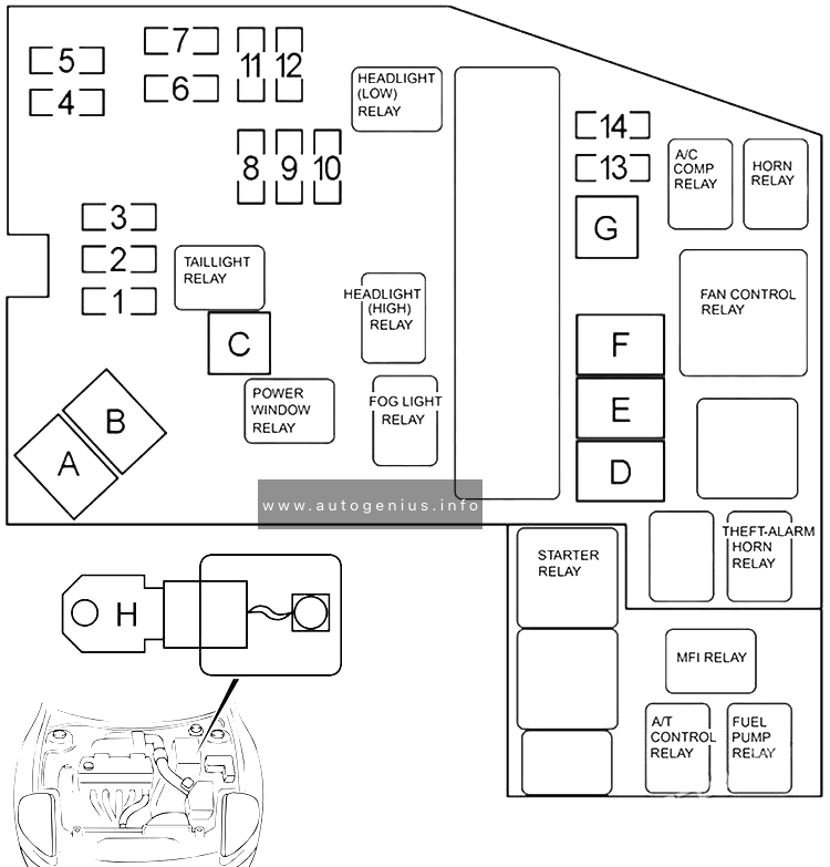
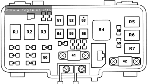
Fuse box diagram
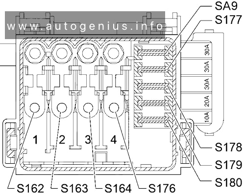
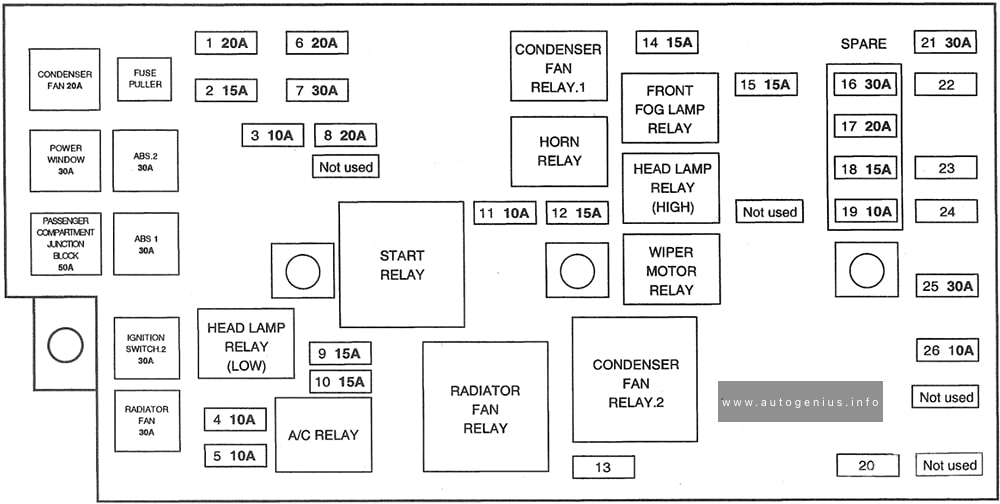
Assignment of the fuses in the engine compartment
| № | Amps | Description |
|---|---|---|
| S162 | 110A | Alternator |
| S163 | 80A | Relay carrier |
| S164 | 50A | Glow plugs (engine) |
| S176 | 50A | Glow plugs (radiator fan) |
| S176 | 30A | Air conditioning system |
| S177 | 30A | ABS control unit |
| S178 | 30A | ABS control unit |
| S179 | 20A | Radiator fan |
| S180 | 10A | Air conditioning system |
| SA9 | 30A | Air conditioner – glow plugs (diesel) |
WARNING: Terminal and harness assignments for individual connectors will vary depending on vehicle equipment level, model, and market.