Volkswagen Polo (6N/6KV; 1994 – 1996) – fuse and relay box diagram
Year od production: 1994, 1995, 1996
This article covers the third-generation Volkswagen Polo (Typ 6N/6KV), manufactured 1997 and 1998. It includes fuse box diagrams for the 1995 through 2002 models, details the locations of the fuse panels within the vehicle, and provides information on the fuse and relay assignments (fuse layout)
Passenger Compartment
Fuse box location
The fuse box is located behind the cover in driver’s storage compartment.
Fuse box diagram
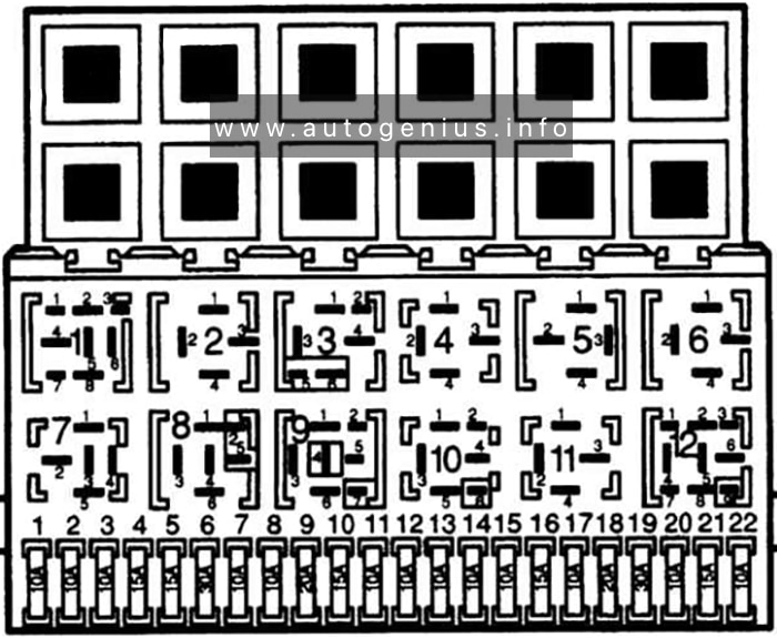
Assignment of the fuses in the instrument panel
| № | Amps | Description |
|---|---|---|
| 1 | 10A | Dipped beam left, headlight range control, left |
| 2 | 10A | Dipped beam right, headlight range control, right |
| 3 | 10A | Number plate light |
| 4 | 15A | Rear window wiper |
| 5 | 15A | Windscreen wipe/wash system, heated washer jets |
| 6 | 20A | Fresh air blower, air conditioner |
| 7 | 10A | Side light and tail light, right |
| 8 | 10A | Side and tail light, left |
| 9 | 20A | Heated rear window |
| 10 | 15A | Rear fog light |
| 11 | 10A | Main beam, left |
| 12 | 10A | Main beam, right |
| 13 | 10A | Horn |
| 14 | 15A | Reversing lights, additional equipment |
| 15 | 10A | Engine electrics |
| 16 | 15A | Dash panel insert |
| 17 | 10A | Turn signals |
| 18 | 20A | Fuel pump, Lambda probe |
| 19 | 30A | Radiator fan |
| 20 | 10A | Brake light |
| 21 | 15A | Interior lights, dash panel insert, self-diagnosis |
| 22 | 10A | Radio system, cigarette lighter |
| Relays: | ||
| 1 | Air conditioner relay | |
| 2 | Rear window wipe/wash relay | |
| 3 | – | |
| 4 | Relief relay for X contact | |
| 5 | – | |
| 6 | Hazard warning light relay | |
| 7 | Headlight washer system relay | |
| 8 | Intermittent wipe/wash relay | |
| 9 | Light switched on. warning buzzer | |
| 10 | Bridge for fog light | |
| 11 | Bridge for horn | |
| 12 | Fuel pump relay Glow plug relay |
|
| Relays above relay plate: | ||
| Window lifter relay and/or folding sliding roof | ||
| Junction box for terminal | ||
| Junction box for terminal | ||
| Starter inhibitor relay | ||
| Intake manifold preheating relay | ||
| Glow period control unit | ||
| 30A | Control unit fuse 1 – ABS (hydraulic pump) | |
| 30A | Control unit fuse 2 – ABS (valves) | |
| Window lifter thermo fuse and/or folding sliding roof | ||
| 50A | Glow plug fuse |
Additional relay carriers:
- Under driver’s seat: Control unit for heated driver’s seat
- Under passenger’s seat: Control unit for heated passenger’s seat
- In engine compartment (left): Radiator fan control unit
WARNING: Terminal and harness assignments for individual connectors will vary depending on vehicle equipment level, model, and market.