Ford Mustang (1999 – 2004) – fuse box diagram
Year of production: 1999, 2000, 2001, 2002, 2003, 2004
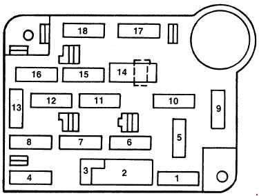
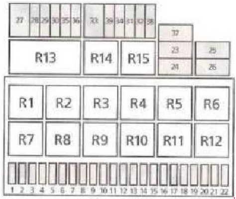
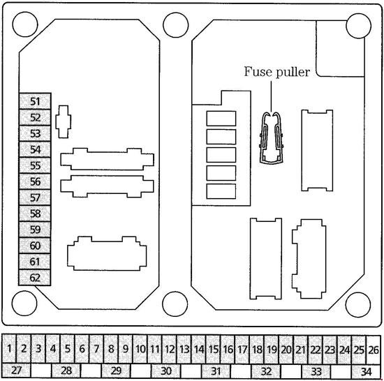
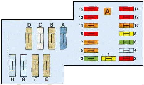
Passenger Compartment Fuse Box
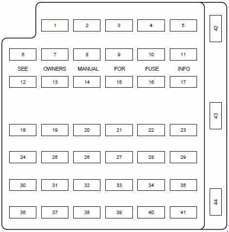
| Fuse | Ampere Rating [A] | Description |
| 1 | 20 | Cigar Lighter |
| 2 | 20 | Engine Controls |
| 3 | — | — |
| 4 | 10 | RH Low Beam Headlamp |
| 5 | 15 | Instrument Cluster, Traction Control Switch |
| 6 | 20 | Starter Motor Relay |
| 7 | 15 | GEM, Interior Lamps |
| 8 | 20 | Engine Controls |
| 9 | 30 | 2002-2004: Mach 460 subwoofers |
| 10 | 10 | LH Low Beam Headlamp |
| 11 | 15 | Back-up Lamps |
| 12 | 2 | 2003-2004: Heated PCV |
| 13 | 15 | Electronic Flasher |
| 14 | — | — |
| 15 | 15 | Power Lumbar |
| 16 | — | — |
| 17 | 15 | Speed Control Servo, Shift Lock Actuator |
| 18 | 15 | Electronic Flasher |
| 19 | 15 | Power Mirror Switch, GEM, Anti-Theft. Relay, Power Door Locks, Door Ajar Switches |
| 20 | 15 | Convertible Top Switch |
| 21 | 5 | Instrument Cluster and Engine Control Memory |
| 22 | — | — |
| 23 | 15 | A/C Clutch, Defogger Switch |
| 24 | 30 | Climate Control Blower Motor |
| 25 | 25 | Luggage Compartment Lid Release |
| 26 | 30 | WiperAVasher Motor, Wiper Relays |
| 27 | 25 | Radio |
| 28 | 15 | GEM, Overdrive Cancel Switch |
| 29 | 15 | ABS Module |
| 30 | 15 | Daytime Running Lamps (DRL) module |
| 31 | 10 | Data Link Connector |
| 32 | 15 | Radio, CD Player (1999-2001), GEM |
| 33 | 15 | Stop Lamp Switch, Speed Control Deactivation Switch |
| 34 | 20 | Instrument Cluster, CCRM, Data Link Connector, Securilock Transciever Module |
| 35 | 15 | Shift Lock Actuator, PCM, Speed Control Servo, ABS Module |
| 36 | 15 | Airbag Control Module |
| 37 | 10 | Adjustable Illumination |
| 38 | 20 | Highbeams |
| 39 | 5 | GEM |
| 40 | — | — |
| 41 | 15 | Brake Lamp |
| 42 | — | — |
| 43 | 20 | Circuit Breaker: Power Windows |
| 44 | — | — |
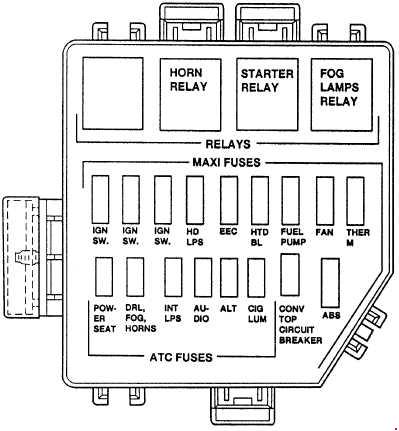
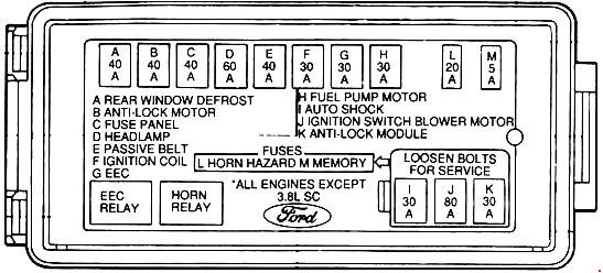
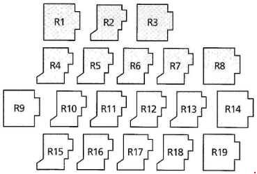
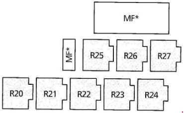
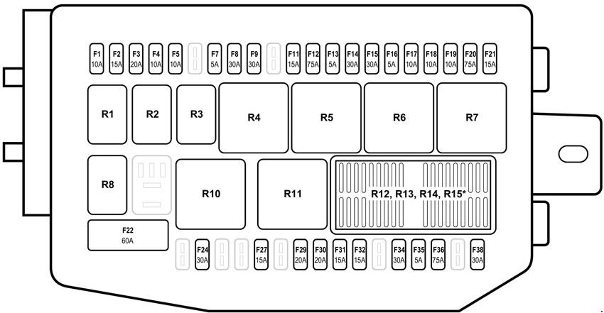
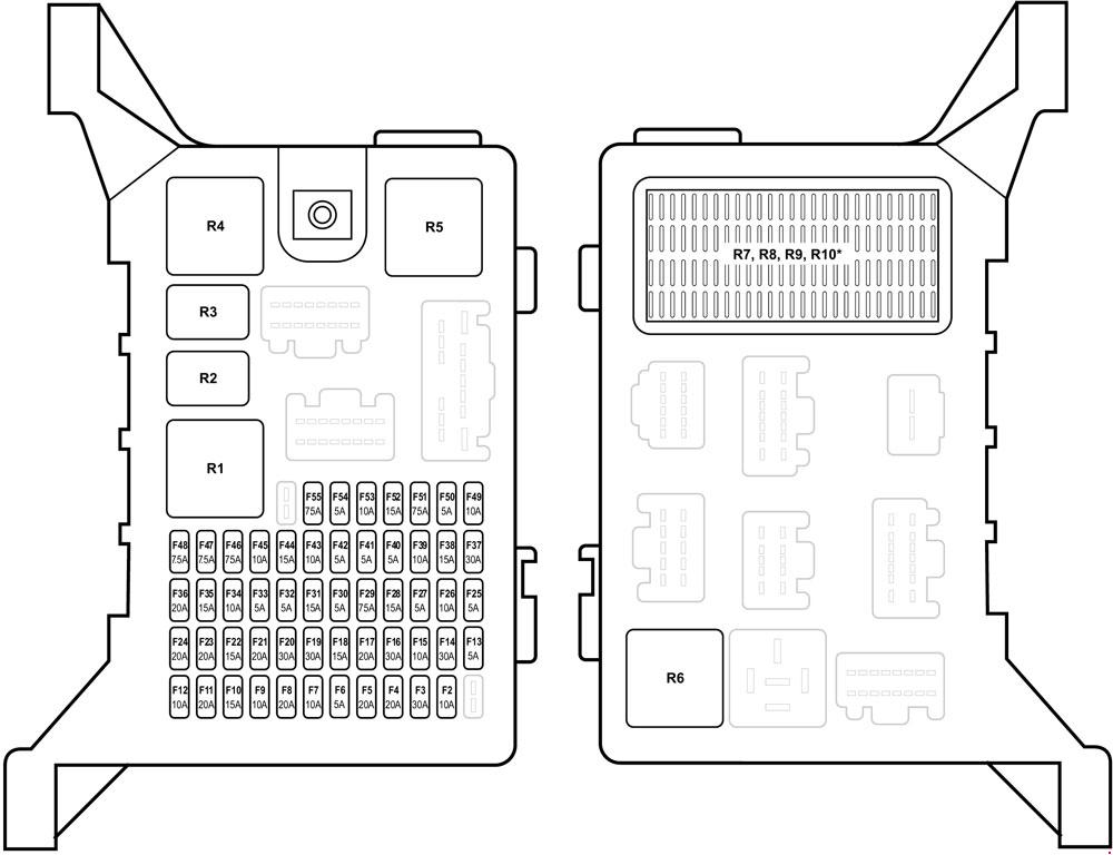
Engine Compartment Fuse Box
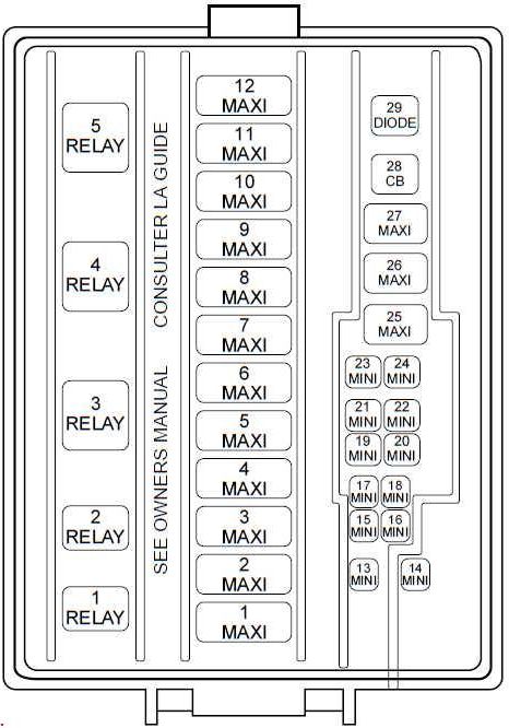
| Number | Ampere Rating [A] | Description |
| 1 | 50 | V8: Electric Cooling Fan Motor |
| 30 | V6: Electric Cooling Fan Motor (Circuit Breaker) | |
| 2 | 30 | Headlamps |
| 3 | 40 | Starter Motor Relay, Ignition Switch |
| 4 | 40 | Ignition Switch |
| 5 | 40 | Ignition Switch |
| 6 | 40 | I/P fuse panel, Instrument cluster, Powertrain Control Module (PCM) |
| 7 | 30 | 1999-2002: Secondary Air Injection (3.8L only) |
| 8 | 50 | ABS Module |
| 9 | 20 | Auxiliary Power Point |
| 10 | 30 | Parklamps |
| 11 | 30 | Rear Window Defrost Control |
| 12 | 40 | Power Windows (1999-2002), Power Locks |
| 13 | 30 | 2003-2004: MACH 1000 right amplifiers |
| 14 | 20 | Fuel Pump |
| 15 | 10 | 1999-2002: Radio |
| 30 | 2003-2004:MACH 1000 left amplifiers | |
| 16 | 20 | Horn |
| 17 | 20 | Anti-Lock Brake System |
| 18 | 25 | Power Seats |
| 19 | 10 | 2002-2004: Intercooler pump (Cobra only) |
| 20 | 20 | Generator |
| 21 | — | — |
| 22 | — | — |
| 23 | — | — |
| 24 | 20 | A/C Pressure |
| 25 | — | — |
| 26 | 30 | PCM |
| 27 | 20 | DRL Module, Foglamp Relay |
| 28 | 25 | Circuit Breaker:Convertible Top |
| Relay |
||
| R1 | Fog Lamp Interrupt |
|
| R2 | Int. Wiper | |
| R3 | Wiper HI/LO | |
| R4 | Starter | |
| R5 | Fog Lamps | |
WARNING: Terminal and harness assignments for individual connectors will vary depending on vehicle equipment level, model, and market.