Ferrari F12Berlinetta – fuse box diagram
Year of production:
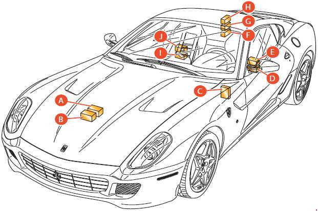
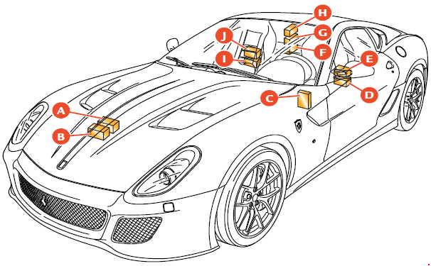
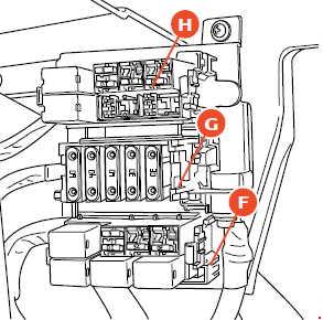
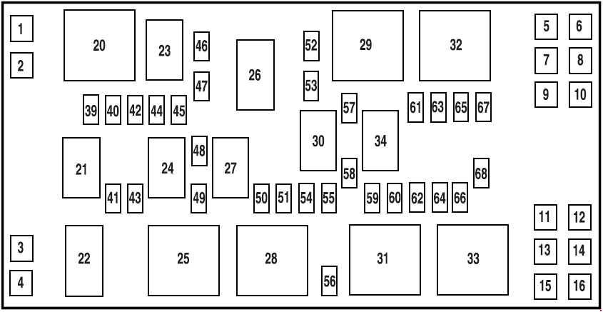
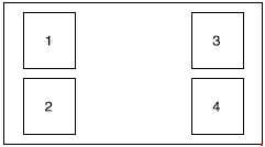
Location
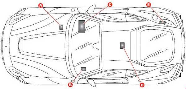
| Number | Location |
| A | Fuses and realys in the battery compartment |
| B | Body computer fuses and relays |
| C | Fuses and relays in the passenger compartment on passenger side |
| D | Fuses and relays on centre console |
| E | Fuses and relays in luggage compartment |
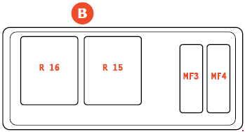
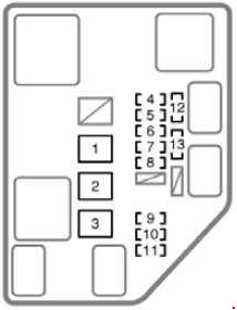
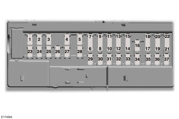
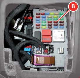
Body Computer fuses and relays
B
| Number | Fuse rating [A] | Description |
| F12 | 15 | Right high beam |
| F13 | 15 | Left high beam |
| F31 | 7,5 | INT/A for dashboard ECU, Body Computer Node and air conditioning and heating relay |
| F32 | 10 | Dome lights, foot well and step lights, Side Marker relay coil and glove compartment button |
| F33 | 30 | Electronically controlled Gearbox Node control unit |
| F35 | 7,5 | Stop light control, clutch control, air conditioning node |
| F36 | 10 | Parking sensors, fuel filler flap relay coil |
| F37 | 10 | Instrument Panel Node |
| F38 | 15 | Luggage compartment lock actuator |
| F39 | 15 | Dashboard ECU devices (NBC interconnection) |
| F40 | 30 | Heated rear window |
| F41 | 15 | Heated nozzle power supply |
| F42 | 7,5 | Alternator |
| F43 | 30 | Windscreen washer/wiper relay power supply |
| F44 | 20 | Passenger seat heating, cigarette lighter |
| F47 | 30 | Driver-side door, driver-side power window |
| F48 | 30 | Passenger-side door, passenger-side power |
| F49 | 7,5 | Rain and twilight sensor, parking sensors, parking brake control, column adjustment control, hazard warning lights. Steering Wheel Node, Differential Control Node, radio, CAN box interface |
| F50 | 7,5 | Airbag Node, weight sensor |
| F51 | 7,5 | Electronically controlled Gearbox Node, ignition button |
| F52 | 15 | Power socket, driver seat heating |
| Relay | ||
| T01 | 20 | Low beam relay |
| T11 | 30 | Heated rear window relay |
| T12 | 30 | Service relay 1 (dependent on INT/A ignition switch) |
| T13 | 50 | Jumper (service power supply 2) |
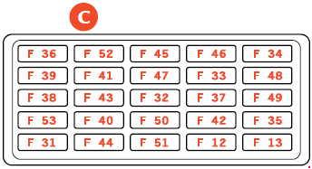
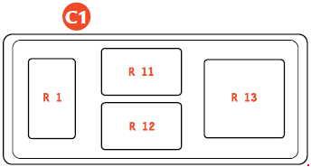
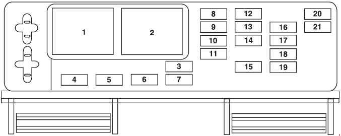
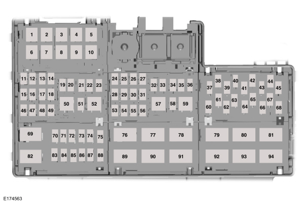
Fuses and relays in passenger compartment on passenger side
C
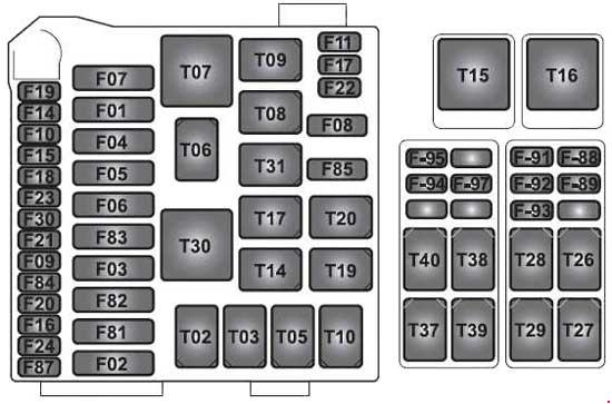
| Number | Fuse rating [A] | Description |
| F01 | 40 | +30 Radiator fan relay 2 |
| F02 | 40 | Bus-Bar power supply for F-102, F-105 |
| F03 | 70 | Bus bar power supply for F-107, F-108, F-91, F-92, F-109, F-104, F-103 |
| F04 | 50 | +30 ABS (pump) |
| F05 | 40 | +30 Air conditioning Node |
| F06 | 40 | +30 Radiator fan relay 1 |
| F07 | 20 | +30 Horn relay |
| F08 | 7,5 | Air conditioning and heating system compressor |
| F09 | 7,5 | +30 Alternator sensing |
| F10 | 30 | +30 Bus bar for F-94, F-95, F-106 |
| F11 | 25 | Left bank oxygen sensor |
| F14 | 15 | +30 High beam relay |
| F15 | 30 | +30 Ignition switch |
| F16 | 25 | +30 Right bank engine control power supply |
| F17 | 25 | +30 Left bank engine control power supply |
| F19 | 20 | +30 Active aerodynamic relay |
| F20 | 30 | +30 Right cylinder bank injection system main |
| F21 | 10 | +30 Active aerodynamic control and front lift power supply |
| F22 | 15 | Left bank (ignition coil) |
| F24 | 15 | Right bank (ignition coil) |
| F30 | 30 | +30 Starting relay |
| F81 | 40 | +30 Fuel pump ESD ECU |
| F82 | 70 | +30 Dashboard ECU and luggage compartment ECU power supply |
| F83 | 50 | +30 Air pump relay |
| F84 | 30 | +30 Suspension Control Node |
| F85 | 25 | Headlight washer |
| F87 | 25 | Right bank oxygen sensors |
| F88 | 10 | +15 Left cylinder bank injection system |
| F89 | 10 | +15 Right cylinder bank injection system |
| F91 | 15 | +30 Tyre pressure node, LH headlight LED module relay |
| F92 | 7,5 | +30 Right headlight LED module relay |
| F94 | 15 | +30 Radio/CAN box/ICP/clock spring/Japan navigation system stabiliser |
| F95 | 10 | +30 Current stabiliser |
| F102 | 10 | +30 ABS (electronic) |
| F105 | 30 | +30 ABS (valves) |
| F106 | 7,5 | +30 Passenger compartment control lighting |
| F107 | 10 | +30 Right cylinder bank injection system power supply |
| F108 | 10 | +30 Left cylinder bank injection power supply |
| F109 | 7,5 | +30 Supplementary stop light relay |
| Relay | ||
| T02 | 30 | High beam relay |
| T03 | 30 | Passenger compartment control lighting relay |
| T05 | 30 | Supplementary stop light relay |
| T07 | 50 | Horn relay |
| T08 | 30 | Air conditioning and headng system compressor relay |
| T09 | 30 | Left cylinder bank injection system main relay |
| T10 | 30 | Right cylinder bank injection system main |
| T14 | 30 | Windscreen washer pump relay |
| T17 | 10 | INT/A relay (devices excluded at ignition) |
| 20 | ||
| T19 | 30 | EPB-activated stop light control relay |
| T20 | 30 | Starting relay |
| T26 | 30 | Windscreen wiper first speed relay |
| T27 | 30 | Windscreen wiper second speed relay |
| T28 | 30 | Active aerodynamic release relay |
| T29 | 30 | Active aerodynamic locking relay |
| T30 | 50 | Air pump relay |
| T31 | 30 | Headlight washer pump relay |
| T38 | 30 | Left headlight LED module power supply |
| T39 | 30 | Right headlight LED module power supply |
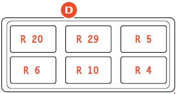
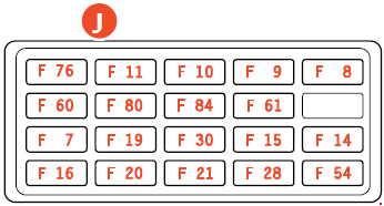
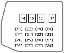
Fuses and relays on centre console
D
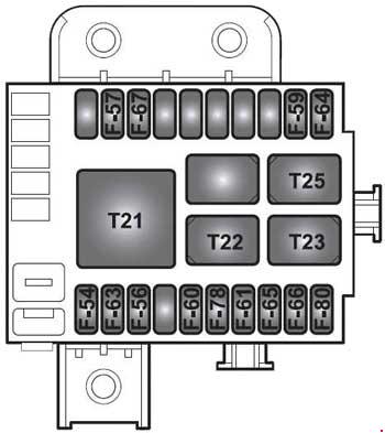
| Number | Fuse rating [A] | Protected component |
| F54 | 30 | +30 HiFi amplifier |
| F56 | 30 | +30 Driving Position Node |
| F57 | 7,5 | Side Markers 1 (LH front and RH rear) |
| F59 | 7,5 | Reverse light power supply |
| F60 | 30 | +30 Passenger Position Node |
| F63 | 20 | +30 Electronically controlled gearbox main relay |
| F64 | 7,5 | Fuel filler flap actuator power supply |
| F65 | 20 | +30 Door lock actuator |
| F66 | 30 | +30 Bus-Bar power supply for F-96, F-100, F-I01 |
| F67 | 7,5 | Side Markers 2 (RH front and LH rear) |
| F80 | 30 | +30 Bus bar power supply for F-97, F-98, F-99 |
| Relay | ||
| T21 | 50 | Side Marker relay |
| T22 | 30 | Reverse light relay |
| T23 | 30 | Fuel filler flap relay |
| T25 | 30 | Electronically controlled gearbox main relay |
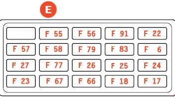
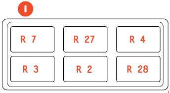
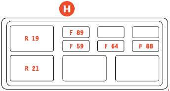
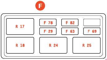
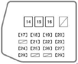
Fuses and relays in luggage compartment
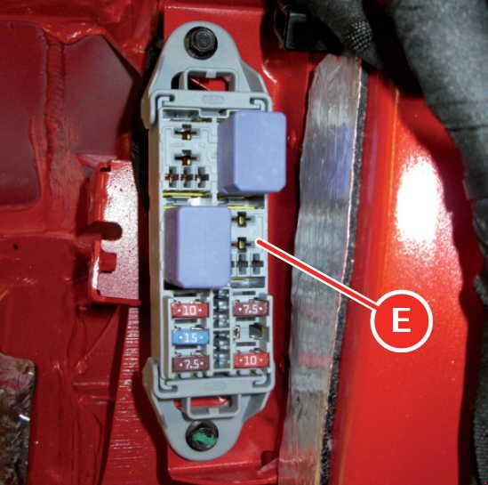
| Number | Ampere ratting [A] | Description |
| F96 | 10 | +30 Luggage compartment lock relay |
| F97 | 10 | +30 Electronic Passenger Position Node, luggage compartment striker plate |
| F98 | 15 | +30 Battery conditioner socket |
| F99 | 7,5 | +30 Semi-automatic Gearbox Node |
| F100 | 7,5 | +30 Driving Position Node, suspension lift ECU |
| Relay | ||
| T40 | 30 | Glove compartment lock relay |
| T41 | 30 | Luggage compartment lid lock relay |
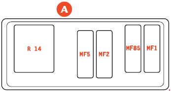
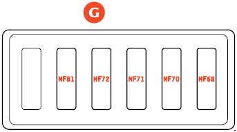
Fuses and relays in battery compartment
A
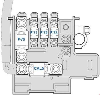
| Number | Ampere ratting [A] | Description |
| CAL5 | CAL5 | Power supply (starter motor and alternator) |
| F70 | 150 | Engine relay and fuse ECU power (SCM) supply |
| F71 | 40 | Front lift pump |
| F72 | 40 | Parking brake power |
| F73 | 70 | Dashboard ECU power |
WARNING: Terminal and harness assignments for individual connectors will vary depending on vehicle equipment level, model, and market.