Audi e-tron GT (2021 – 2025) – fuse and relay box diagram – US version
Year of production: 2021, 2022, 2023, 2024, 2025
The Audi e-tron GT, a battery-electric executive car, has been in production since 2020. In this article, you’ll find fuse box diagrams for the 2021, 2022, 2023, 2024 and 2025 models. You’ll also learn where the fuse panels are located within the vehicle and find detailed information on the fuse assignments (fuse layout).
Passenger compartment
Fuse box location
The fuses are located in the left and right footwells, as well as at the left and right front sides of the cockpit.
Left footwell fuse panel
Fuse Box Diagrams
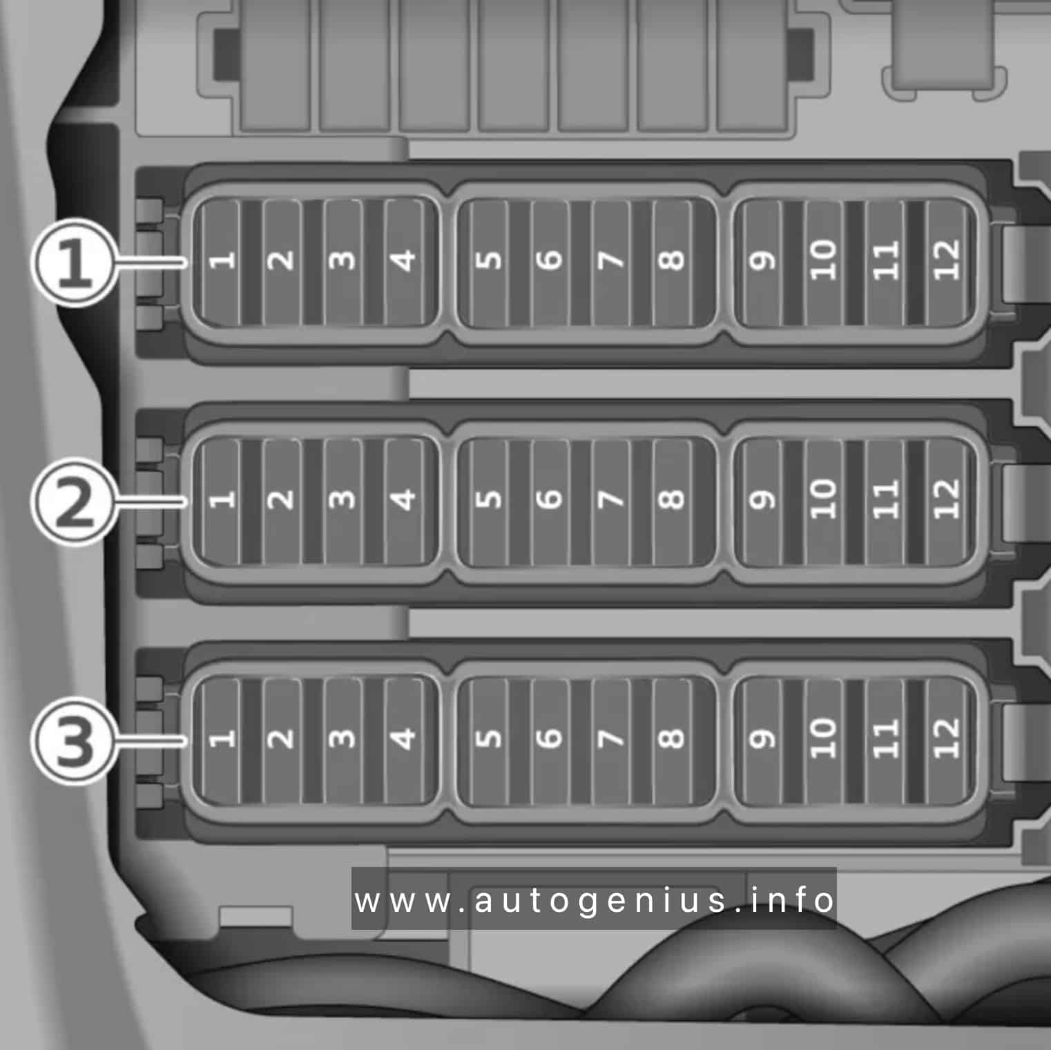
Assignment of the fuses in the left footwell
| № | Equipment |
|---|---|
| Fuse panel 1 (brown) | |
| 1 | Heating circuit coolant pump |
| 3 | Thermal management |
| 5 | Vehicle electrical system control module |
| 6 | Vehicle electrical system control module |
| 7 | Light/rain/humidity sensor |
| 8 | Remote controlled parking |
| 9 | Roof electronics control module |
| 10 | Vehicle electrical system control module |
| 12 | Data exchange and telematics control module |
| Fuse panel 2 (red) | |
| 1 | Driver assistance systems control module |
| 2 | Left rear door control module |
| 3 | Thermal management |
| 4 | Windshield wipers |
| 5 | Electronic Stabilization Control (ESC) |
| 7 | Left front safety belt |
| 8 | Vehicle electrical system control module |
| 9 | Vehicle electrical system control module |
| 10 | Left headlight |
| 11 | Left front door control module |
| 12 | Vehicle electrical system control module |
| Fuse panel 3 (white) | |
| 3 | Vehicle electrical system control module |
| 4 | Diagnostic connection |
| 6 | Left front intersection assistant |
| 7 | Brake system pressure reservoir |
| 8 | Rearview mirror |
| 9 | Data exchange and telematics control module |
| 10 | Power supply |
| 11 | Power supply |
Right footwell fuse panel
Fuse Box Diagrams

Assignment of the fuses in the right footwell
| № | Equipment |
|---|---|
| Fuse panel 4 (brown) | |
| 1 | Vehicle electrical system control module |
| 3 | Vehicle electrical system control module |
| 4 | Windshield wipers |
| 5 | Vehicle electrical system control module |
| 6 | Right rear door control module |
| 7 | Driver assistance systems control module |
| 8 | Right front door control module |
| 9 | Airbag control module |
| 10 | Right front safety belt |
| 11 | Remote controlled parking |
| 12 | Vehicle electrical system control module |
| Fuse panel 5 (red) | |
| 1 | Diagnostic interface |
| 3 | Thermal management |
| 4 | Right headlight |
| 5 | Vehicle electrical system control module |
| 6 | Vehicle electrical system control module |
| 7 | Night vision assist control module |
| 8 | Driver assistance systems front camera |
| 9 | Rear climate control system control panel |
| 11 | Right front intersection assistant |
| Fuse panel 6 (white) | |
| 1 | Diagnostic connection |
| 2 | Diagnostic interface |
| 3 | Brake system pressure reservoir |
| 4 | Vehicle electrical system control module |
| 5 | Front power electronics control module |
| 6 | Ionizer |
| 7 | Power supply |
| 8 | Power supply |
| 9 | Voltage converter |
| 10 | Power steering |
| 12 | Adaptive cruise assist |
Left cockpit fuse panel
Fuse Box Diagrams
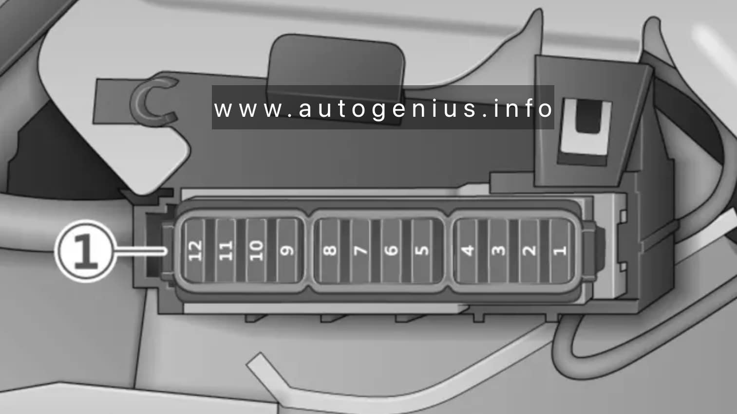
Assignment of the fuses in the left cockpit
| № | Equipment |
|---|---|
| Fuse panel 1 (black) | |
| 1 | Front climate control system control panel |
| 2 | Light switch |
| 3 | Climate control system control module |
| 4 | Head-up display control module |
| 5 | Steering column electronics |
| 6 | Steering column adjustment |
| 8 | Instrument cluster |
| 11 | Rear climate control system control panel |
| 12 | Steering column electronics, steering wheel heating |
Right cockpit fuse panel
Fuse Box Diagrams
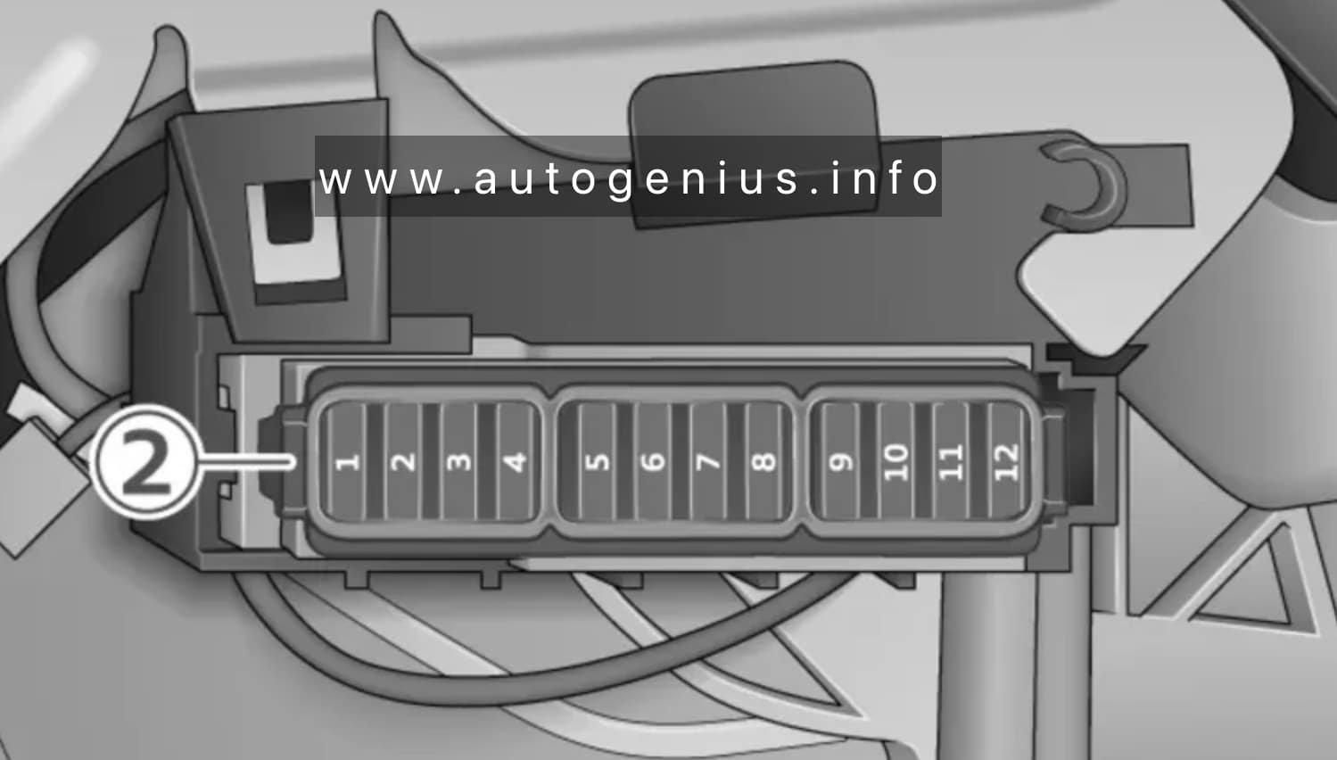
Assignment of the fuses in the right cockpit
| № | Equipment |
|---|---|
| Fuse panel 2 (brown) | |
| 1 | Audi phone box |
| 2 | Infotainment system |
| 3 | Center display, volume control |
| 4 | Audi connect apps control module |
| 5 | Audi music interface |
| 6 | Climate control system blower |
| 8 | Selector lever positions |
| 12 | Diagnostic connection |
WARNING: Terminal and harness assignments for individual connectors will vary depending on vehicle equipment level, model, and market.