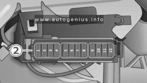
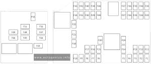
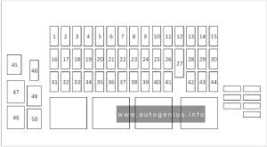
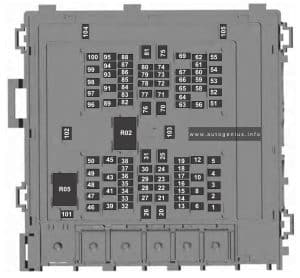
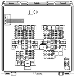
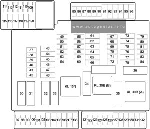
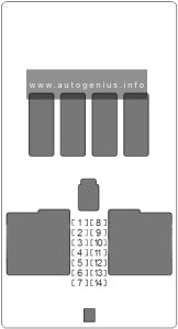
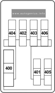
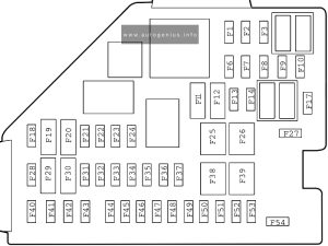
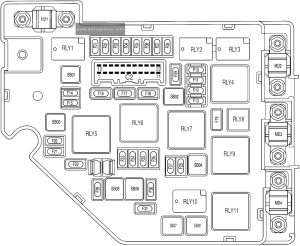
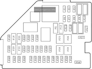
This article focuses on the second-generation MG MG3, following its second facelift, produced from 2018 to 2023. It includes fuse box diagrams for the 2019 through 2023 models, provides details on the locations of the fuse panels inside the vehicle, and explains the function of each fuse (fuse layout).
MG MG5 EV (2020 – 2024) – fuse and relay box diagram
Year of production: 2020, 2021, 2022, 2023, 2024
The MG MG5 EV, a battery electric subcompact car, has been in production from 2020 to the present. This article provides fuse box diagrams for the 2020, 2021, 2022, 2023, and 2024 models, details the locations of the fuse panels inside the vehicle, and explains the function of each fuse (fuse layout)
Passenger compartment fuse box
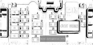
Fuse Box Diagram
MG MG5 EV (2020 – 2024) – fuse and relay box diagram – passenger compartment fuse box
Assignment of the fuses in the passenger compartment
№
Amps
Protected components
F1
15A
Front Console Power Socket
F2
5A
Interior Mirror, Rear Console USB Charging Ports
F3-F17
–
–
F18
5A
2020-2022: TBOX, Vehicle Control Unit, Sensing Diagnostic Module (Airbag), Shifter Control Unit, Instrument Pack.
2023-2023: Vehicle Control Unit, Sensing Diagnostic Module (Airbag), Shifter Control Unit, Instrument Pack, Front Detection Radar, Front View Control Module
F19
5A
2020-2022: AC Front Panel
2023-2024: Digital Audio Broadcasting Module
F20
10A
AC Control Module
F21
10A
Front Right Seat Heater
F22
5A
Diagnostic Socket
F23
10A
Front Left Seat Heater
F24
5A
PEPS Control Module
F25
–
–
F26
30A
2020-2022: Front Left Window Lift, Rear Right Window Lift
2023-2024: Front Right Window Lift, Rear Right Window Lift
F27
–
–
F28
5A
Backup Immobilizer Coil
F29
15A
Entertainment System
F30
5A
Instrument Pack
F31
5A
EPB Switch
F32
5A
2020-2022: Rain Light Sensor
2023-2024: Driver Door Switch Pack, Tyre Pressure Monitoring System
F33
10A
Sensing Diagnostic Module (Airbag)
F34
10A
2020-2022: Driver Door Switch Pack, Gateway
2023-2024: Gateway
F35
–
–
F36
15A
2023: Towing Device Reserved Interface
F37
25A
Driver Electric Seat Adjustment
F38
–
–
F39
40A
Blower
F40-F43
–
–
F44
5A
2020-2022: Radio Broadcasting Reception Module
2023-2024: 360 Around View Module
F45
10A
2020-2022: Electronic Steering Column Lock
F46
10A
2023-2024: Electronic Steering Column Lock
F47
5A
High Voltage Electric Heater
F48
–
–
F49
5A
TBOX
F50
10A
Gateway
F51
5A
2020-2022: Shifter Control Unit, Tyre Pressure Monitoring System
2023-2024: Shifter Control Unit
F52
5A
2020-2022: Door Mirrors and Headlamp Levelling Adjustment Switch
F53
5A
Pedestrian Alert Control Module
F54
–
–
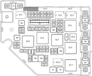
Engine compartment fuse box
Fuse Box Diagram
MG MG5 EV (2020 – 2024) – fuse and relay box diagram – engine compartment fuse box
Assignment of the fuses in the engine compartment
№
Amps
Protected components
F1
On-board Network Terminal Resistance
F2
On-board Network Terminal Resistance
F3
30A
Body Control Module
F4
20A
Body Control Module
F5
15A
Body Control Module
F6
5A
Charging Plug Latch
F7
5A
Vehicle Control Unit
F8
30A
2020-2022: Electric Parking Motor Control Unit
F8
5A
2023-2024: Electrical Battery Sensor
F9
15A
Horn Relay, Horn
F10
10A
2023-2024: Electric Vehicle Communication Controller
F11
15A
2020-2022: High Voltage Battery Pack, Electric Vehicle Communication Controller, Battery Heater
2023-2024: High Voltage Battery Pack
F12-F24
–
–
F25
30A
2020-2022: Driver Door Switch Pack, Driver Window Lift, Rear Left Window Lift
2023-2024: Front Left Window Lift, Rear Left Window Lift
F26
30A
Stability Control System (Valve)
F27
15A
Windscreen Washer System
F28
10A
Body Control Module
F29
20A
Body Control Module
F30
25A
Front Wiper System
F31
10A
Power Electronic Box
F32
25A
Body Control Module
F33
15A
Superlock System
F34
15A
Main relay, Power Electronic Box Water Pump, Brake Lamp Switch
F35
5A
Combined Charging Unit
F36
5A
2020-2022: Electric Air Conditioning Compressor
2023-2024: Electric Air Conditioning Compressor, Charging Status Lamp
F37
10A
2020-2022: Main Beam Relay, Main beam
2023-2024: Daytime Running Lamp
F38
15A
Rear Wiper System
F39
15A
High-Voltage Battery Pack Coolant Pump
F40-F42
–
–
F43
7.5A
Heated Exterior Rearview Mirror
F44
25A
Heated Rear Window
F45
–
–
F46
5A
2020-2022: Door Mirrors and Headlamp Levelling Adjustment Switch, Manual Headlamp Levelling
2023-2024: Headlamp Levelling Adjustment Switch, Manual Headlamp Levelling
F47
–
–
F48
5A
Charging Flap Motor
F49-F52
–
–
A
80A
Electric Power Steering Module
B
–
–
C
40A
Stability Control System (Pump)
D
–
–
E
40A
2023-2024: Electric Parking Motor Control Unit
F
30A
Electrical Parking Brake Control Module
G
50A
Cooling Fan
H
50A
iBooster
M
150A
Combined Charging Unit
L
30A
Electronic Parking Brake Control Module
K
100A
Passenger Compartment Fuse Box
WARNING: Terminal and harness assignments for individual connectors will vary depending on vehicle equipment level, model, and market.
Mazda MX-30 EV (2021 – 2023) – fuse and relay box diagram
Year of production: 2021, 2022, 2023
The Mazda MX-30 (DR), a subcompact crossover, has been available since 2020. This article provides fuse box diagrams for the Mazda MX-30 EV models from 2021, 2022, and 2023, along with information on the locations of the fuse panels inside the vehicle and the function and layout of each fuse
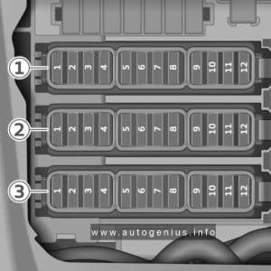
Passenger compartment fuse box
Fuse Box Location
It is located behind the cover on the left side of the vehicle.
Mazda MX-30 EV (2021 – 2023) – fuse and relay box location – passenger compartment fuse box
Fuse Box Diagram
Mazda MX-30 EV (2021 – 2023) – fuse and relay box location – passenger compartment fuse box
Assignment of the fuses in the passenger compartment
№
Amps
PROTECTED COMPONENT
F1
–
–
F2
–
–
F3
–
–
F4
15A
Power door locks (Driver)
F5
15A
Power door locks (Passenger)
F6
–
–
F7
–
–
F8
–
–
F9
30A
Power windows (Driver)
F10
30A
Power windows (Passenger)
F11
30 A
Power seat (Driver) (Some models)
F12
–
–
FI 3
15A
Audio
F14
20A
Front seat warmer (Some models)
F15
15A
Liftgate lock
F16
15A
Illumination
F17
10A
Brake lights
F18
10A
Reverse lights
F19
10A
Rear turn signal lights
F20
10A
Taillights
F21
10A
Taillights
F22
7.5A
Air Bag
F23
–
–
Engine compartment fuse box
Fuse Box Location
Open the fuse block cover by unhooking the tabs and lifting up on the cover.
Mazda MX-30 EV (2021 – 2023) – fuse and relay box location – engine compartment fuse box
Fuse Box Diagram
Mazda MX-30 EV (2021 – 2023) – fuse and relay box diagram – engine compartment fuse box
Assignment of the fuses in the engine compartment
№
Amps
PROTECTED COMPONENT
F1
30A
Accessory sockets
F2
20A
Windshield wiper deicer (Some models)
F3
–
–
F4
–
–
F5
–
–
F6
–
–
F7
20A
BEV control system
F8
10A
Motor control system
F9
15A
BEV control system
F10
10A
BEV control system
F11
7.5A
Air conditioner
F12
10A
BEV control system
F13
–
–
FI 4
–
–
F15
–
–
F16
15A
For protection of various circuits
F17
15A
2021-2022: Water pump
2023: BEV control system
F18
15A
Accessory sockets
F19
60A
Power steering system
F20
15A
Headlight (LH) 1
F21
15A
Headlight (RH) 1
F22
15A
2021-2022: Keyless system
2023: For protection of various circuits
F23
30A
ABS, Dynamic stability control system
F24
15A
Headlight (LH) 2
F25
15A
Headlight (RH) 2
F26
7.5A
On board diagnostics
F27
25A
For protection of various circuits
F28
25A
For protection of various circuits
F29
15A
Windshield washer
F30
10A
2023: Accessory sockets (Some models)
F31
15A
Horn
F32
–
–
F33
–
–
F34
20A
BEV control system
F35
50A
ABS, Dynamic stability control system
F36
30A
2021-2022: Parking lock
2023: BEV control system
F37
30A
Rear window defogger
F38
50A
For protection of various circuits
F39
–
–
F40
40A
Air conditioner
F41
–
–
F42
20A
Windshield wiper
F43
–
–
F44
30A
2021-2022: Accessory sockets
2023: For protection of various circuits
F45
10A
BEV control system
F46
15A
Audio
F47
15A
For protection of various circuits
F48
7.5A
Air bag
F49
15A
Instrument cluster
F50
15A
2021-2022: Room light
2023: For protection of various circuits
F51
25A
Audio
F52
10A
Moonroof (Some models)
F53
15A
BEV control system
F54
10A
i-ACTIVSENSE
F55
–
–
F56
–
–
WARNING: Terminal and harness assignments for individual connectors will vary depending on vehicle equipment level, model, and market.
The Mazda CX-30, a compact crossover SUV, has been in production since 2019. In this article, you’ll find fuse box diagrams for the 2019, 2020, 2021, 2022 and 2023 models, along with information on the locations of the fuse panels inside the vehicle and details on each fuse’s function and layout.
Passenger compartment fuse box
Fuse Box Location
It is located behind the cover on the left side of the vehicle.
Year of production: 2019, 2020, 2021, 2022, 2023, 2024
This article focuses on the fourth-generation Mazda 3 (BP), produced from 2019 to the present. It includes fuse box diagrams for the 2019 through 2024 models, details the locations of the fuse panels within the vehicle, and provides information on the function and layout of each fuse and relay.
Passenger compartment fuse box
Fuse box location
It is located on the left side of the vehicle, behind the cover.
This article examines the seventh‑generation Subaru Legacy and the sixth‑generation Subaru Outback, produced from 2020 onward. You’ll find fuse box diagrams for the 2020 and 2021 models, guidance on locating the fuse panels within the vehicle, and a detailed overview of each fuse’s function and layout.
Passenger compartment fuse box
Fuse Box Location
It is located behind the cover below and to the left of the steering wheel.
Lincoln Aviator (U611; 2020 – 2024) – fuse and relay box diagram
Year of production: 2020, 2021, 2022, 2023, 2024
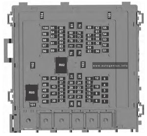
This article covers the second-generation Lincoln Aviator (U611), produced from 2019 onward. It includes fuse box diagrams for the 2020, 2021, 2022, 2023 and 2024 models, provides details on the locations of the fuse panels inside the vehicle, and explains the purpose and layout of each fuse and relay.
Passenger compartment fuse panel
Fuse box location
The fuse panel is located under the instrument panel to the left of the steering column.
Windshield and rear window washer pump relay power.
17
5A
2021-2023: Charge status indicator.
18
30A
Starter motor.
21
10A
Headlamp leveling motors.
Adaptive headlamps.
22
10A
Electric power assisted steering module.
23
10A
Anti-lock brake system module with integrated park brake.
24
10A
Powertrain control module.
Hybrid powertrain control module.
25
10A
Air quality sensor.
Particulate matter sensor.
360 camera with park aid.
Rear view camera.
Blind spot information system.
Adaptive cruise control module.
26
15A
Transmission control module.
28
40A
Anti-lock brake system valves with integrated park brake.
29
60A
Anti-lock brake system pump with integrated park brake.
30
30A
Driver seat module.
31
30A
Passenger seat module.
32
20A
Not used (spare).
33
20A
Rear cargo area power point.
34
20A
Main console bin power point.
35
20A
Not used (spare).
36
40A
Power inverter.
38
30A
Climate controlled seat module.
41
30A
Power liftgate module.
42
30A
Trailer brake control module.
43
60A
Body control module.
44
10A
Brake on and off switch.
46
15A
2021-2023: Battery charger control module.
50
40A
Heated backlite.
54
20A
Heated steering wheel.
55
20A
Trailer tow park lamps.
57
30A
Trailer tow battery charge.
58
10A
Trailer tow backup lamps.
61
15A
Multi-contour seat module.
62
15A
Headlamp washer pump.
64
40A
Four-wheel drive module.
69
30A
Front window wiper motor.
71
15A
Rear window wiper motor.
72
20A
Air suspension module.
73
30A
Driver door module.
78
—
Not used.
79
—
Not used.
80
20A
Left-hand front electronic door.
82
20A
Right-hand front electronic door.
88
20A
Rear blower motor.
91
20A
Trailer tow lighting module.
95
15A
2021-2023: Integrated spark control.
96
15A
Not used (spare).
97
10A
2021-2023:
Electric A/C.
High voltage positive temperature coefficient heater.
Year of production: 2017, 2018, 2019, 2020, 2021, 2022, 2023, 2024
The Opel Grandland X was produced from 2017 to 2024 and underwent a restyling during its production run. It is also known as the Vauxhall Grandland. In this post, you’ll find detailed information about the fuses and relays in the Grandland, including fuse box diagrams, their locations.
Passenger compartment fuse box
Fuse Box Location
The main fuse box is located on the left side at the bottom of the instrument panel.
Engine computer l Charge pump (for ER6EDT) – ignition coils (EB2ADTS and EP6FADTX)
F21
30
Starter
F22
40
Reserve – Taxi
F23
40
Starter/Alternator
F24
40
Fuse box in passenger compartment 5
F25
40
Interior fuse box 3
F26
15/20
Heater
F27
25
Intelligent Switching Unit (Right Low Beam Headlight – Right Reversing Lights – Left Fog Lights – Left Rear Parking Lights – Third Brake Light.)
F28
30
Power supply for urea pump and urea tube heating resistor (UCE or DV5R) – Nox sensor (DW10F) – Engine computer (EP6FADTX) – (BlueInjection, AdBlue)
F29
40
Windshield wiper
F30
80
Pre-heating unit
F31
80
Switching and protection unit
F32
80
Power steering, Left low beam headlight – Static turn lights – Side turn indicators – Left turn indicators – Front left and rear right side lights – Left brake lights – License plate lights.
Relay
R1
Engine control computer / Euro6 diesel (SCR module power supply)
R2
Air Conditioning Compressor/Heated Windshield
R3
Starter / thermal preconditioning
R4
Fog lights/daytime running lights
R5
Air conditioner fan
R6
Starter
R7
Front wiper
R8
Front wiper
R9
Battery fuse box
Fuse Box Location
A high power fuse box is attached to the positive terminal of the battery.
Opel Grandland (2017 – 2021) – fuse and relay box diagram
Year of production: 2017, 2018, 2019, 2020, 2021, 2022, 2023, 2024
The Opel Grandland X was produced from 2017 to 2024 and underwent a restyling during its production run. It is also known as the Vauxhall Grandland. In this post, you’ll find detailed information about the fuses and relays in the Grandland, including fuse box diagrams, their locations.
Passenger compartment fuse box
Fuse Box Location
The main fuse box is located on the left side at the bottom of the instrument panel.
Opel Grandland (2017 – 2024) – fuse and relay location – passenger compartment
Fuse Box Diagram
Opel Grandland (2017 – 2024) – fuse and relay diagram – passenger compartment
Type 1
Assignment of the fuses in the passenger compartment (type 1)
№
Description
1
Interior mirror / Electric power steering wheel / Selective drive control / Radar / Diesel exhaust system
3
Trailer Position Control Module
4
Signal
5
Window washer (front/rear)
6
Window washer (front/rear)
7
Rear socket
8
Rear wiper
10
Door lock/rear door lock
11
Door lock/rear door lock
12
Stop-Start System / Diagnostic Connector Module / Brake System
13
Infotainment system / Climate control system
14
Alarm siren
15
Climate control system
16
Stop-start/Brake system
17
Instrument panel
18
Parking assistant
19
Steering Column Electrical System / Steering Wheel Controls
21
Anti-theft alarm
22
Camera / Rain sensor / Automatic lighting control
23
Seat belt reminder
24
Automatic Transmission /Advanced Parking Assist / Panoramic View System
Engine computer l Charge pump (for ER6EDT) – ignition coils (EB2ADTS and EP6FADTX)
F21
30
Starter
F22
40
Reserve – Taxi
F23
40
Starter/Alternator
F24
40
Fuse box in passenger compartment 5
F25
40
Interior fuse box 3
F26
15/20
Heater
F27
25
Intelligent Switching Unit (Right Low Beam Headlight – Right Reversing Lights – Left Fog Lights – Left Rear Parking Lights – Third Brake Light.)
F28
30
Power supply for urea pump and urea tube heating resistor (UCE or DV5R) – Nox sensor (DW10F) – Engine computer (EP6FADTX) – (BlueInjection, AdBlue)
F29
40
Windshield wiper
F30
80
Pre-heating unit
F31
80
Switching and protection unit
F32
80
Power steering, Left low beam headlight – Static turn lights – Side turn indicators – Left turn indicators – Front left and rear right side lights – Left brake lights – License plate lights.
Relay
R1
Engine control computer / Euro6 diesel (SCR module power supply)
R2
Air Conditioning Compressor/Heated Windshield
R3
Starter / thermal preconditioning
R4
Fog lights/daytime running lights
R5
Air conditioner fan
R6
Starter
R7
Front wiper
R8
Front wiper
R9
Battery fuse box
Fuse Box Location
A high power fuse box is attached to the positive terminal of the battery.
Fuse Box Diagram
Opel Grandland (2017 – 2024) – fuse and relay diagram – battery fuse box
Assignment of the fuses in battery fuse box
№
Amp
Description
1
60
Electrical control unit for two-speed fan motor
2
100
Fuse box
3
80
Power steering
4
80
Interior fuse box
5
80
Interior fuse box
WARNING: Terminal and harness assignments for individual connectors will vary depending on vehicle equipment level, model, and market.