Seat Leon (mk4; 2021 – 2025) – fuse and relay box diagram
Year of production: 2021, 2022, 2023, 2024, 2025
This article covers the fourth-generation SEAT Leon (KL1/KL8), produced from 2020 onward. It includes fuse box diagrams for the 2021, 2022, 2023, 2024 and 2025 models, details the locations of the fuse panels within the vehicle, and provides information on the function of each fuse (fuse layout).
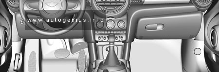
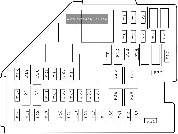
Passenger Compartment Fuse Box
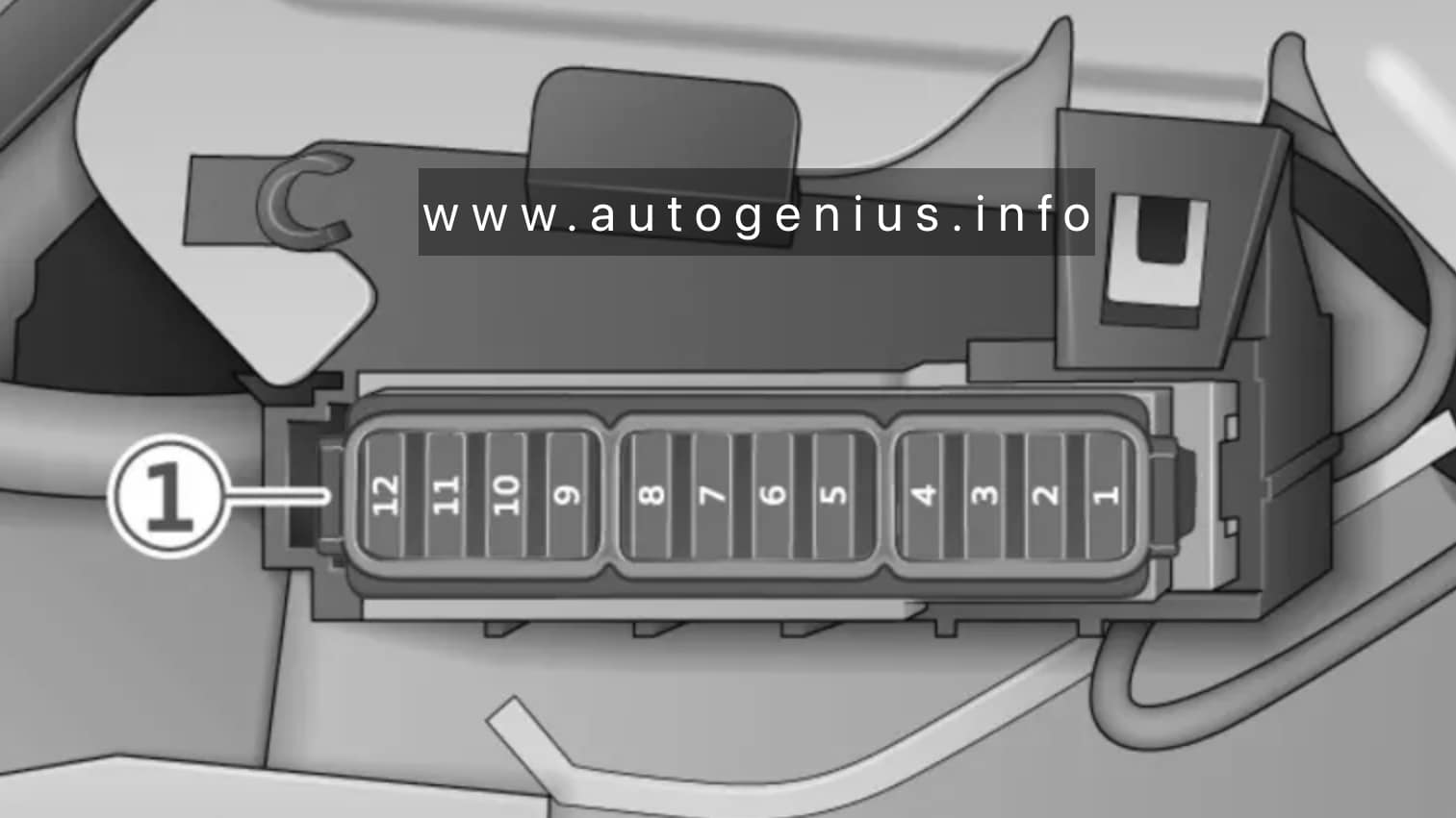
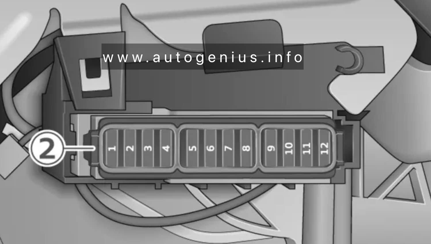
Fuse Box Location
The fuse box is located behind the cover on the driver’s side.
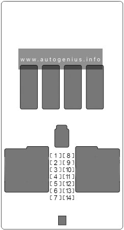
Fuse Box Diagram
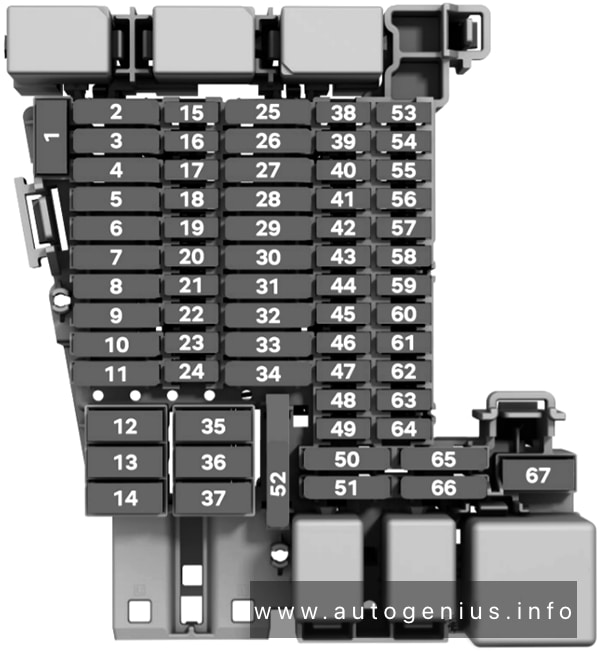
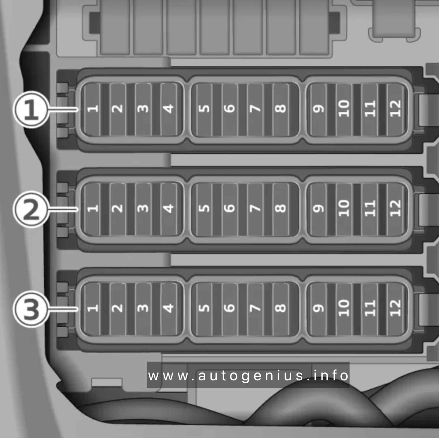
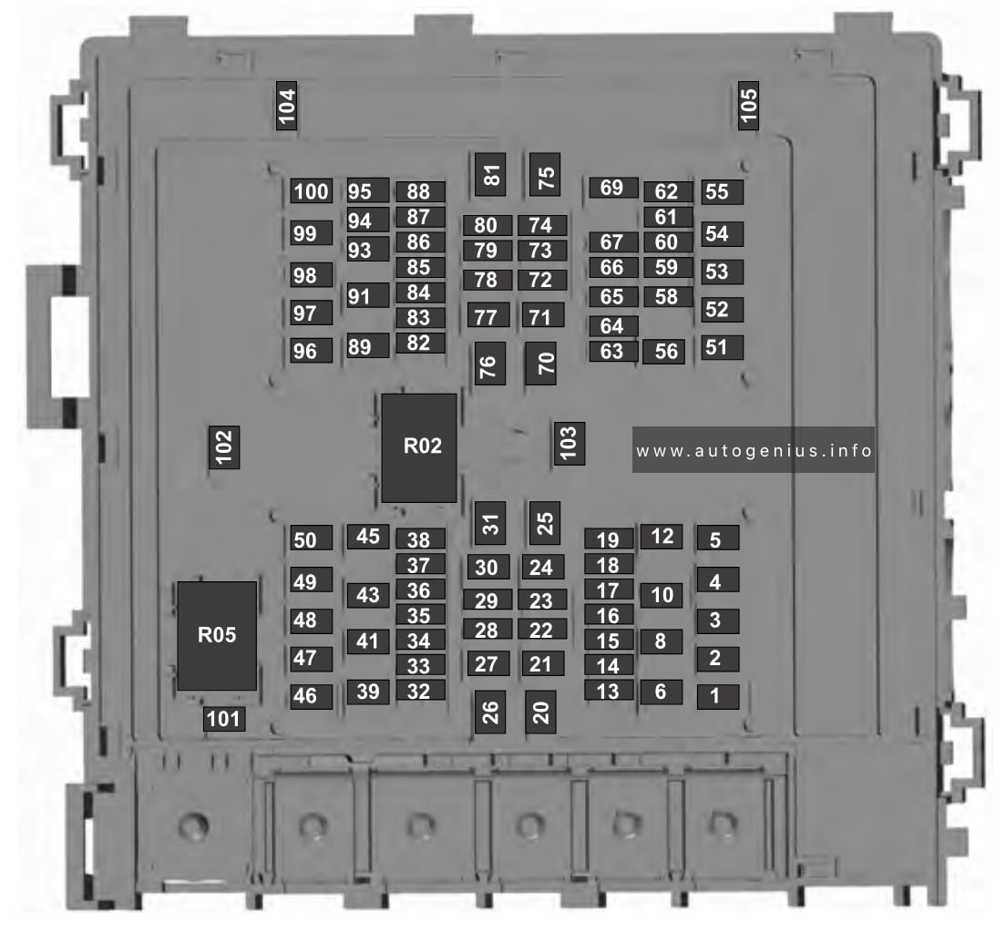
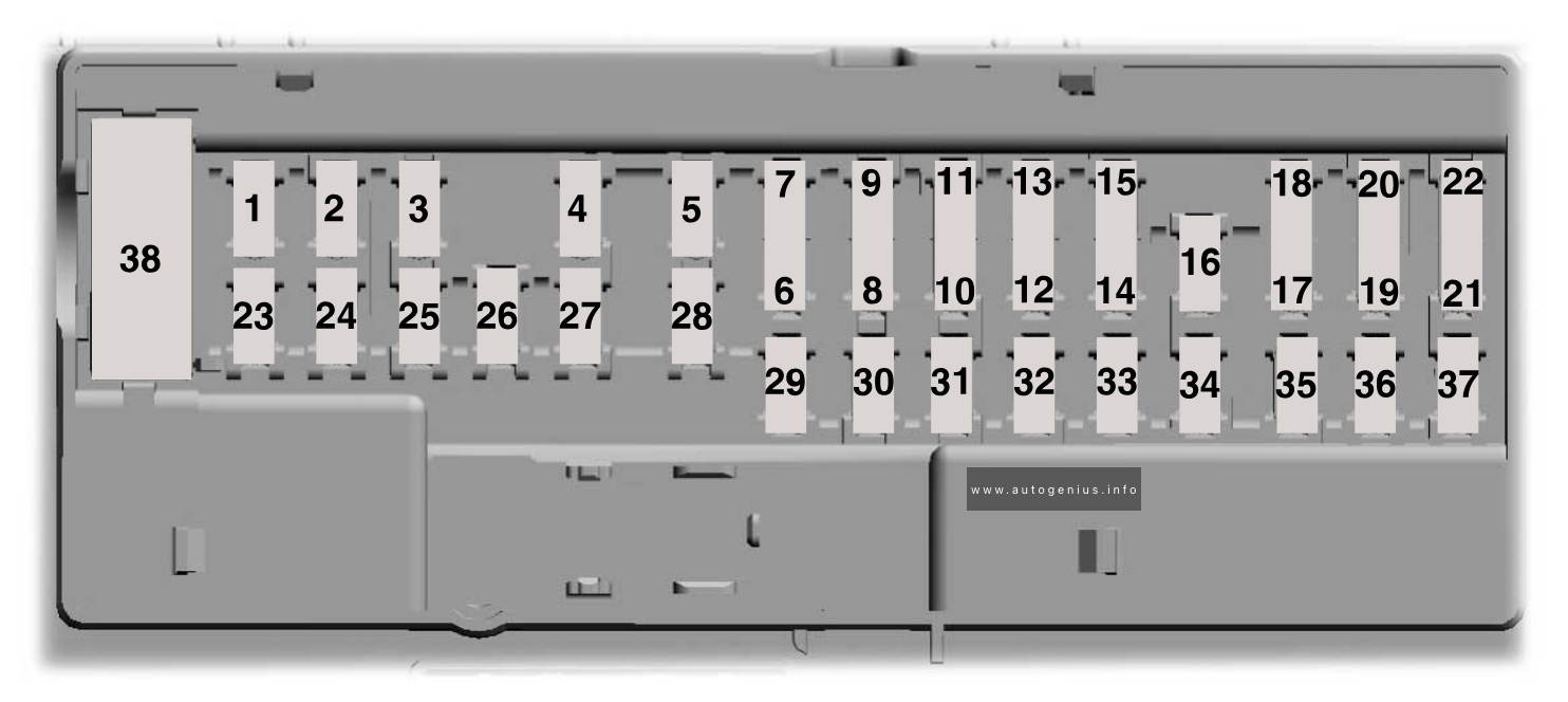
Assignment of the fuses in the instrument panel
| № | Consumers | Amps |
|---|---|---|
| 1 | – | – |
| 2 | – | – |
| 3 | Trailer | 25A |
| 4 | SCR, Adblue | 20A |
| 5 | Automatic gearbox lever | 25A |
| 6 | Interior light | 30A |
| 7 | Heated seats | 30A |
| 8 | Sunroof | 20A |
| 9 | Left door | 30A |
| 11 | Trailer | 15A |
| 12 | Right lights | 40A |
| 13 | Central locking | 40A |
| 14 | External Ethernet Amplifier | 30A |
| 15 | – | – |
| 16 | Airbag | 7.5A |
| 17 | SCR, engine relay, 1.5 | 10A |
| 18 | KESSY (keyless locking) | 7.5A |
| 19 | Instrument panel | 7.5A |
| 20 | Connectivity Box | 7.5A |
| 21 | Rear camera | 7.5A |
| 22 | – | – |
| 23 | – | – |
| 24 | 4×4 Haldex Control Unit | 15A |
| 25 | RGS+EBSS front seat belts | 25A |
| 26 | Right door | 30A |
| 27 | RGS+EBSS front seat belts | 25A |
| 28 | PHEV, Switching off the high voltage system for rescue tasks, Identified by a yellow label | 10A |
| 29 | Trailer | 15A |
| 30 | Radio | 30A |
| 31 | Trailer | 25A |
| 32 | – | – |
| 33 | – | – |
| 34 | 230V socket | 30A |
| 35 | Left lights | 40A |
| 36 | Air conditioner fan | 40A |
| 37 | Electric rear lid | 30A |
| 38 | – | – |
| 39 | Heated steering wheel | 10A |
| 40 | Alarm horn | 7.5A |
| 41 | Gateway | 7.5A |
| 42 | Automatic gearbox lever | 7.5A |
| 43 | Air conditioning and heating control panel, rear window heating, AC compressor | 10A |
| 44 | Diagnosis, handbrake switch, light switch, reverse light, interior lighting, lit-up door sill | 7.5A |
| 45 | Steering column | 7.5A |
| 46 | Radio display | 7.5A |
| 47 | Driving mode | 10A |
| 48 | USB | 7.5A |
| 49 | – | – |
| 50 | – | – |
| 51 | – | – |
| 52 | 12V socket | 20A |
| 53 | – | – |
| 54 | – | – |
| 55 | – | – |
| 56 | – | – |
| 57 | – | – |
| 58 | Parking sensors, park distance control unit, front camera, radar | 7.5A |
| 59 | Reverse switch, clima sensor, electrochromic mirror | 7.5A |
| 60 | Diagnosis, headlight control unit, headlight adjuster | 7.5A |
| 61 | Starter motor, clutch sensor | 7.5A |
| 62 | – | – |
| 63 | – | – |
| 64 | – | – |
| 65 | Sound amplifier | 10A |
| 66 | Rear window wiper | 15A |
| 67 | Heated rear window | 30A |
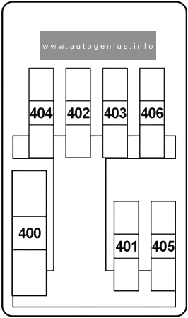
| In-line fuses: | ||
| 230V rear power sockets | 30A | |
| Electric driver’s seat |
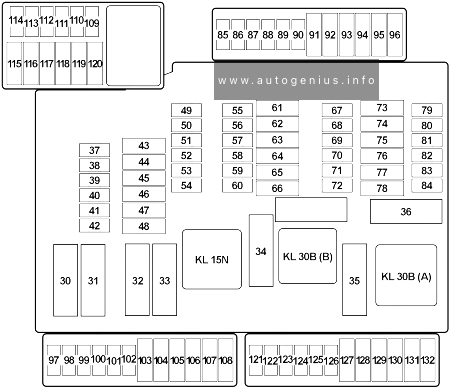
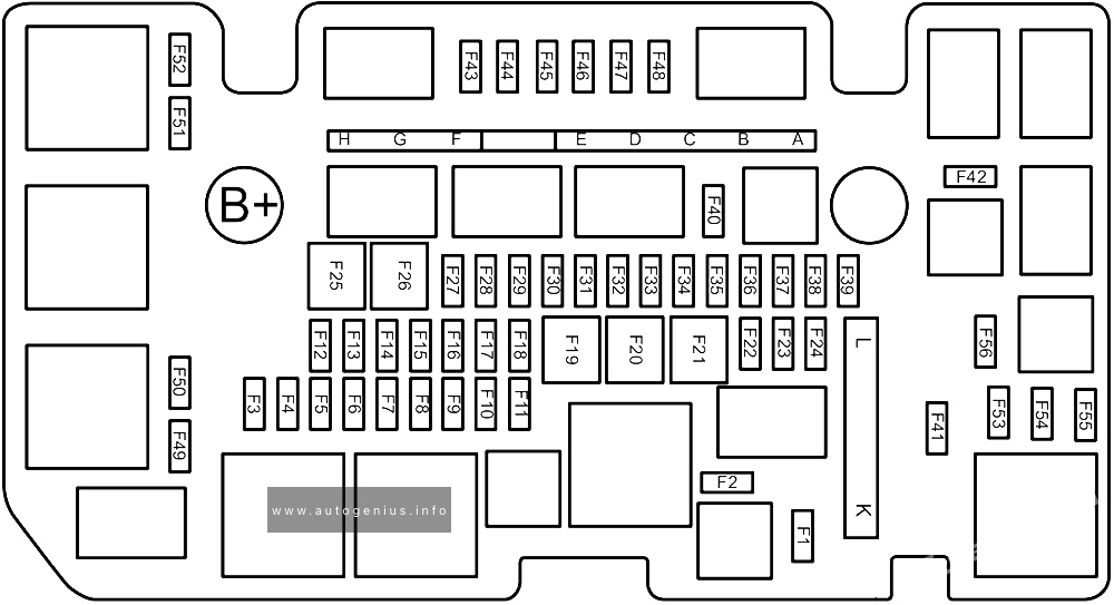
Engine Compartment Fuse Box
Fuse Box Diagram
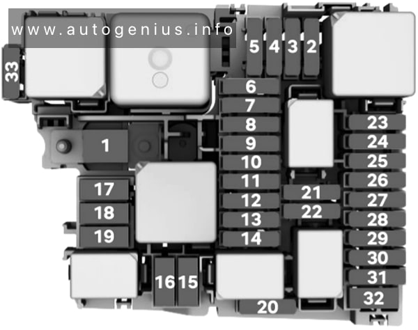
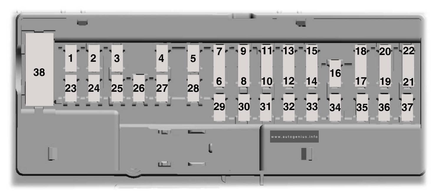
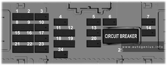
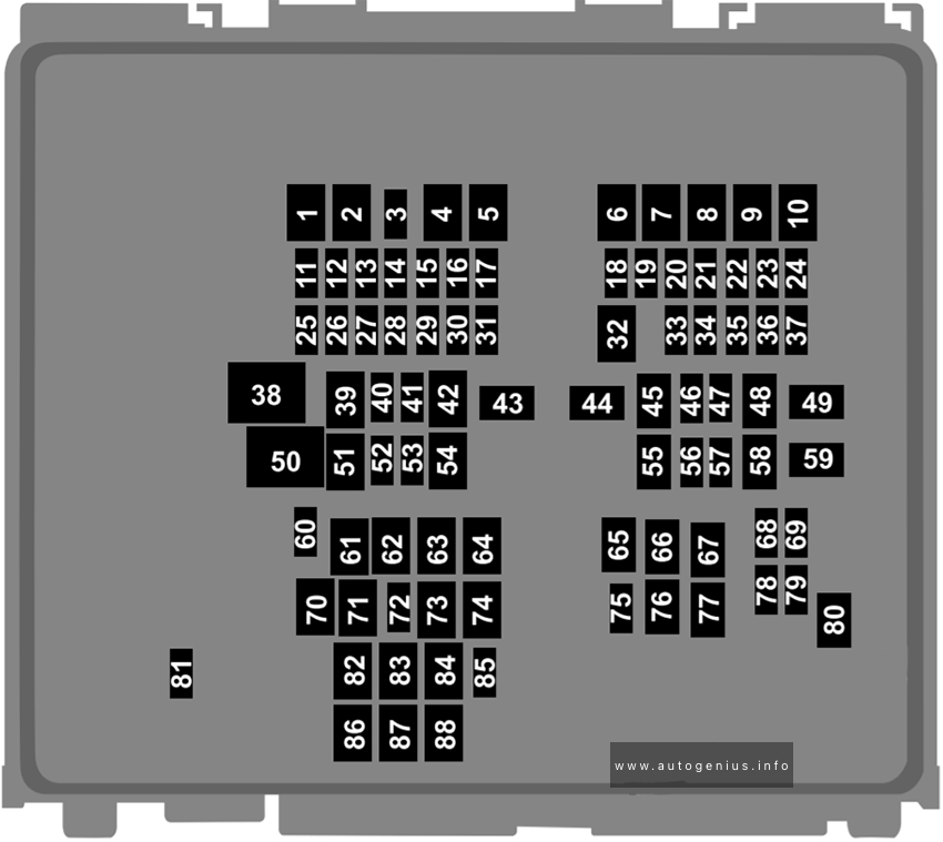
Assignment of the fuses in the engine compartment
| № | Consumers | Amps |
|---|---|---|
| 1 | – | – |
| 2 | Engine control unit | 7.5A |
| 3 | Fuel pump control unit | 7.5A/10A/20A |
| 4 | Left headlight KL 30 Signal | 15A |
| 5 | Right headlight KL 30 Signal | 15A |
| 6 | – | – |
| 7 | Automatic gearbox pump | 30A |
| 8 | KL 30 Signal brake servo | 40A |
| 9 | Horn | 15A |
| 10 | Front windscreen washer | 30A |
| 11 | PHEV Climate | 7.5A |
| 12 | Automatic gearbox control unit | 15A/30A |
| 13 | ESP control unit | 25A |
| 14 | Auxiliary heater | 20A |
| 15 | ESP control unit | 40A |
| 16 | PHEV, Automatic gearbox unit | 50A |
| 17 | PTC | 40A |
| 18 | PTC | 40A |
| 19 | – | – |
| 20 | Front electronic differential | 15A |
| 21 | Engine control unit | 7.5A |
| 22 | Starter motor | 30A |
| 23 | Engine control unit (diesel/petrol) | 15A |
| 24 | Engine sensors | 7.5A/10A |
| 25 | Engine sensors | 7.5A/10A |
| 26 | Engine power supply | 7.5A/10A/15A |
| 27 | Lambda probe | 10A/15A |
| 28 | Engine | 10A/20A |
| 29 | Fuel pump control unit | 15A/20A/30A |
| 30 | Pressure pump 1.0 | 10A |
| 31 | – | – |
| 32 | – | – |
| 33 | PTC | 40A |
WARNING: Terminal and harness assignments for individual connectors will vary depending on vehicle equipment level, model, and market.