MG ZS EV (2019 – 2021) – fuse and relay box diagram
Year of production: 2019, 2020, 2021
The pre-facelift MG ZS EV, a subcompact electric crossover, was produced from 2019 to 2021. This article includes fuse box diagrams for the 2019, 2020, and 2021 models, provides details on the locations of the fuse panels inside the vehicle, and explains the function of each fuse (fuse layout).
Passenger Compartment Fuse Box
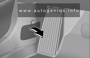
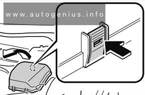
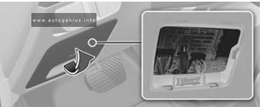
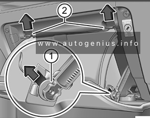
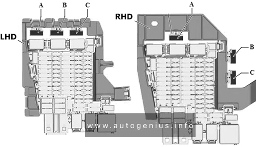
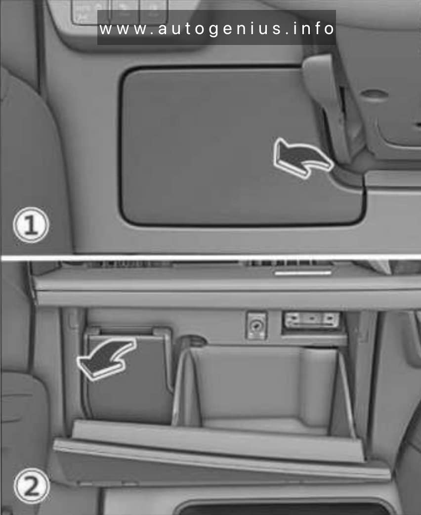
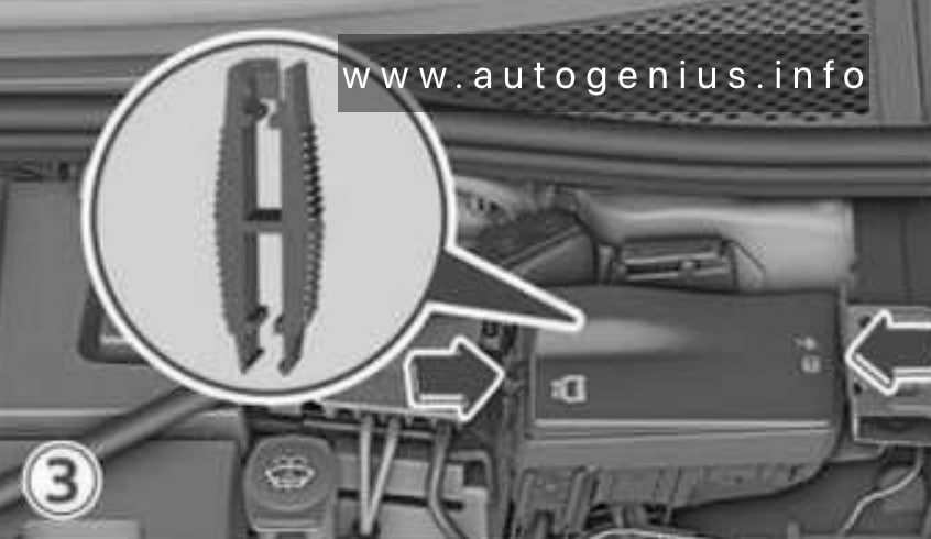
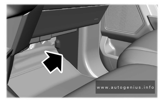
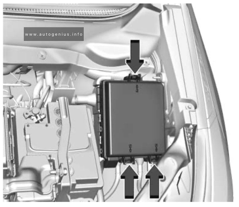
Fuse Box Location
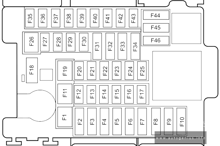
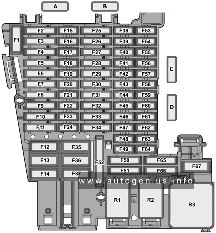
The fuse panel is located below the glove box at the front passenger side.
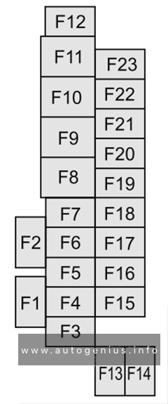
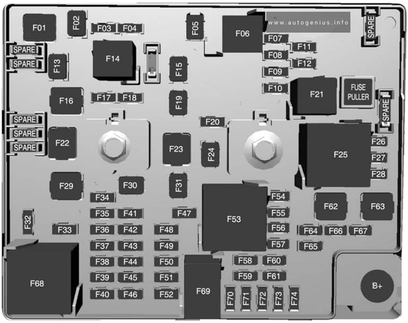
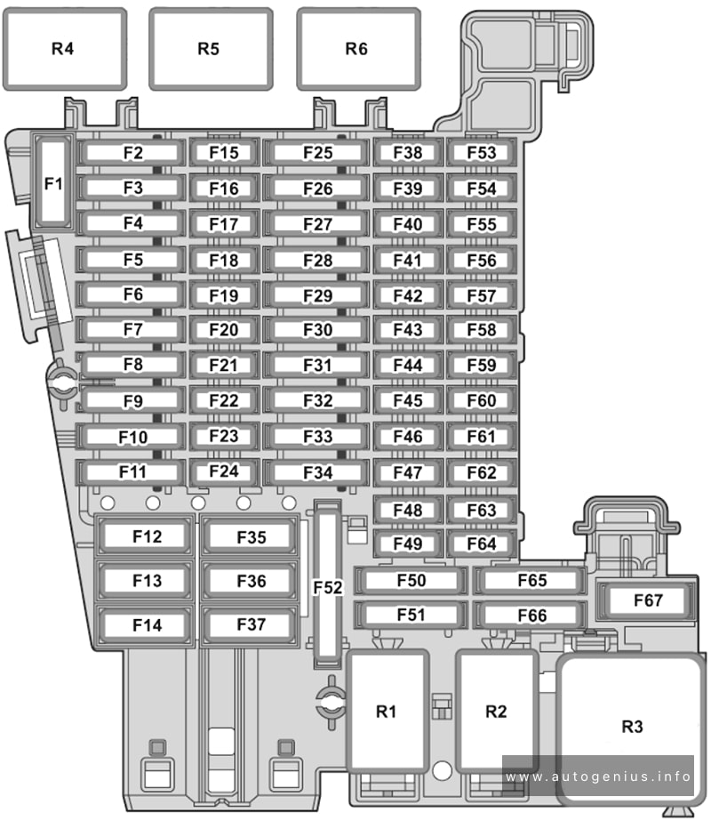
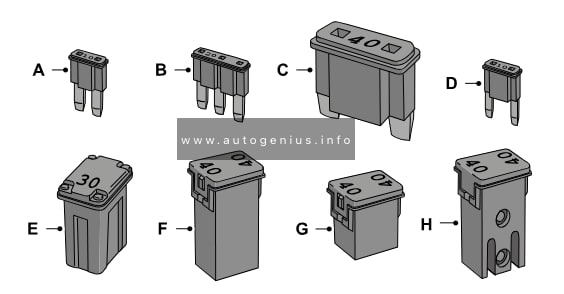
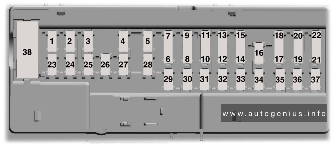
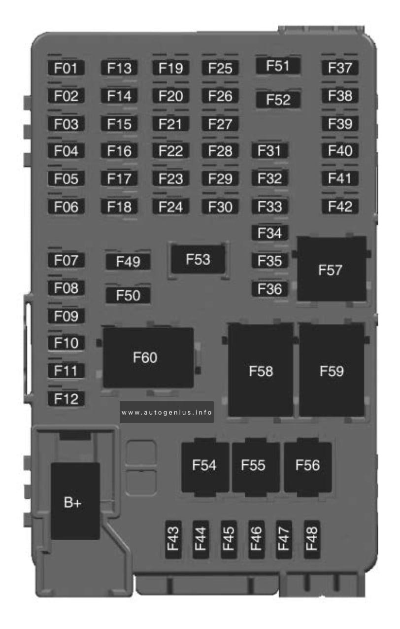
Fuse Box Diagram
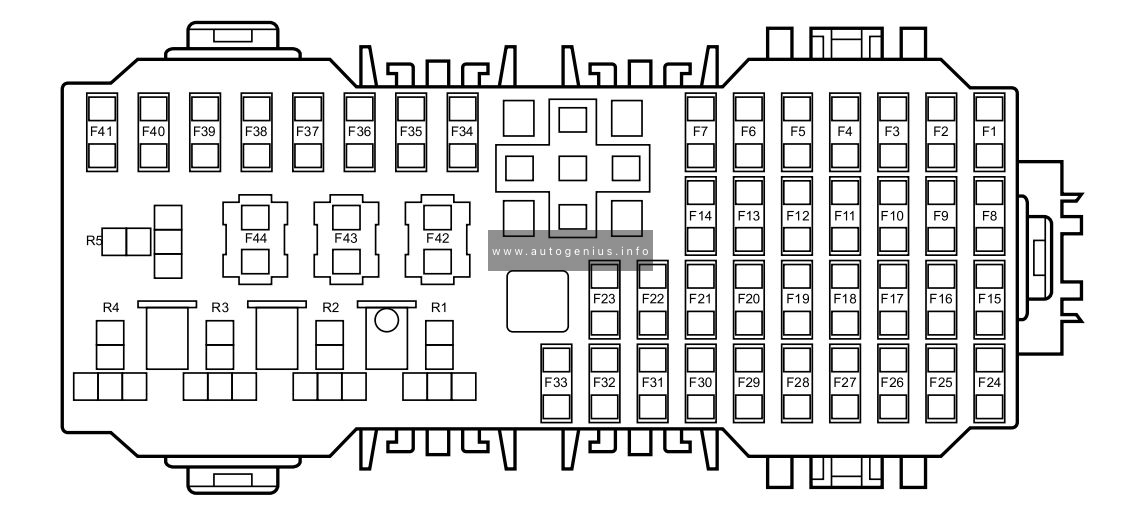
Assignment of the fuses in the passenger compartment
| No. |
А |
Function |
| F1 | 5A | Charging Plug Unlock Relay, Charging Plug Lock Relay |
| F2 | 10A | Diagnostic Socket |
| F3 | 5A | Charger, EVCC |
| F4 | 15A | Front Wash Relay, Rear Wash Relay |
| F5 | 5A | SDM |
| F6 | 5A | HV PTC, ESS PTC |
| F7 | 10A | ESS (High Voltage Battery) |
| F8 | 5A | TPMS, EPB Switch |
| F9 | 5A | VCU |
| F10 | 10A | PACM |
| F11 | 5A | PEPS |
| F12 | – | – |
| F13 | 30A | Driver Seat Adjust Switch |
| F14 | 5A | IMMO Coil |
| F15 | 15A | Front Power Socket |
| F16 | 5A | Rear USB Charge Module, Master Light Switch, Headlamp Assembly |
| F17 | – | – |
| F18 | 30A | Rear Left Window Lift Switch |
| F19 | 30A | Passenger Window Lift Switch |
| F20 | 30A | Rear Right Window Lift Switch |
| F21 | 30A | Driver Window Lift Motor |
| F22 | 10A | Heated Mirrors |
| F23 | 25A | Rear Windshield Assembly |
| F24 | 20A | FICM, IFP, DAB |
| F25 | 15A | ETC, ACFP |
| F26 | 5A | Instrument Pack |
| F27 | 10A | Driver Door Switch Pack, Master Light Switch |
| F28 | 5A | RLS, Master Radar |
| F29 | 10A | Gateway |
| F30 | 10A | Gateway |
| F31 | 30A | Sunroof ECU |
| F32 | 30A | Sunroof ECU |
| F33 | 5A | SCU |
| F34 | 10A | ESCL |
| F35 | 15A | Super Lock Relay |
| F36 | — | — |
| F37 | — | — |
| F38 | — | — |
| F39 | — | — |
| F40 | — | — |
| F41 | — | — |
| F42 | 30A | EPB |
| F43 | 30A | EPB |
| F44 | – | – |
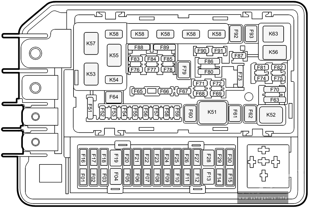
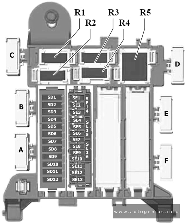
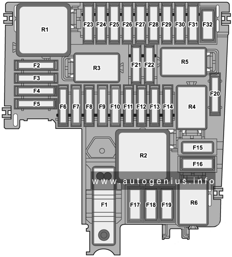
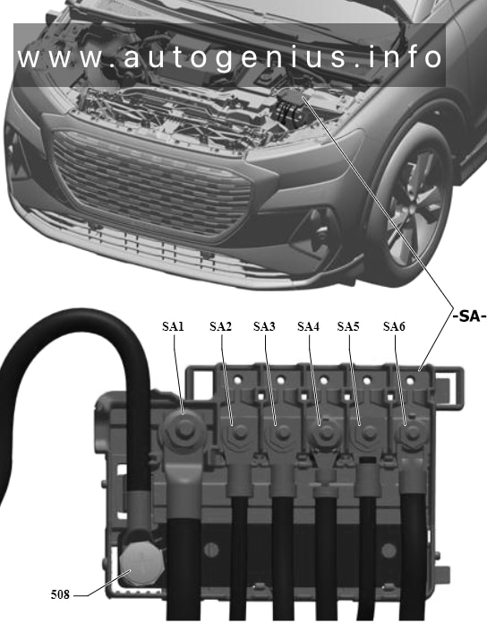
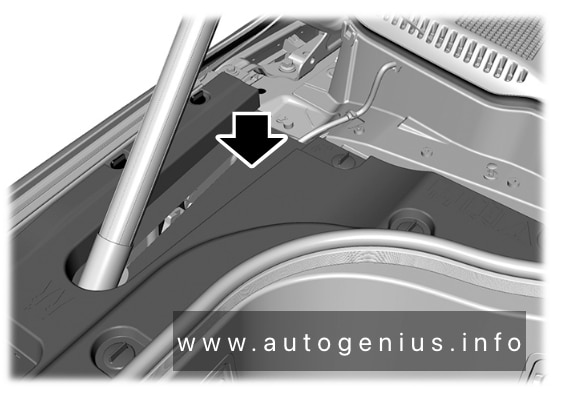
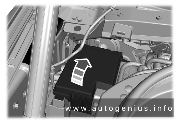
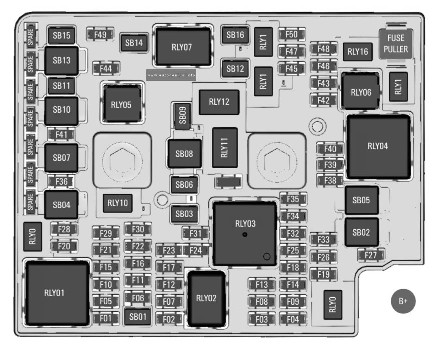
Engine Compartment Fuse Box
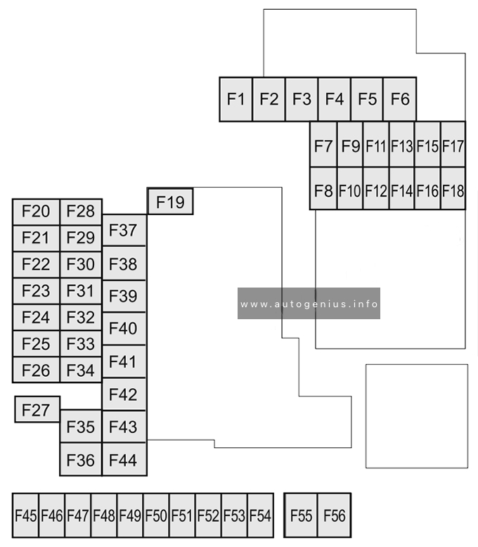
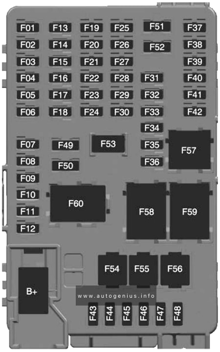
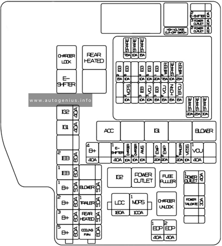
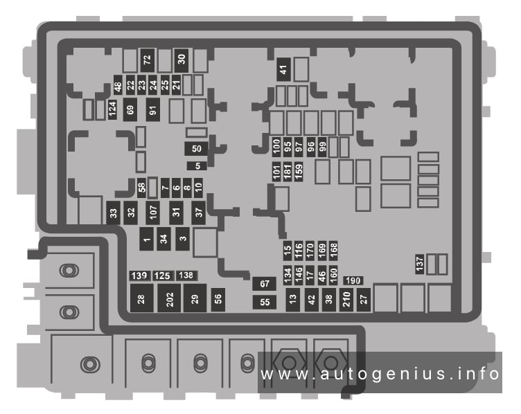
Fuse Box Diagram
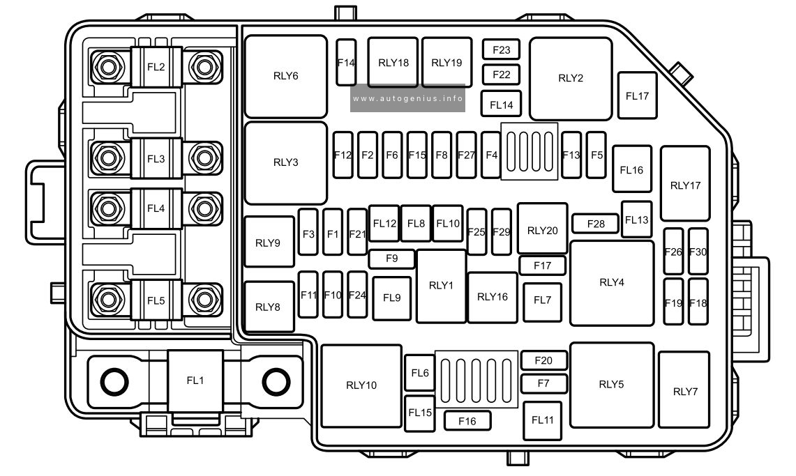
Assignment of the fuses in the engine compartment
| № | Amps | Function |
|---|---|---|
| FL1 | I50A | PEB |
| FL2 | 80A | EPS |
| FL3 | 40A | Cooling Fan Relay Pack |
| FL4 | 80A | Passenger Compartment Fusebox Fuse F18, F19, F20, F21, F34, F35, F42, F43 |
| FL5 | 80A | Passenger Compartment Fusebox Fuse F1, F2, F3, F4, F5, F6, F7, F8, F9, F10, F11, F13, F14, F24, F25, F26, F27, F28, F29, F30, F31, F32, F33, HRW Relay |
| FL6 | 25A | SCS Valve |
| FL7 | 30A | Blower Motor, ETC |
| FL8 | 20A | BCM |
| FL9 | 40A | SCS Pump |
| FL10 | 30A | BCM |
| FL11 | – | – |
| FL12 | 20A | BCM |
| FL13 | – | – |
| FL14 | – | – |
| FL15 | 30A | KLR Relay |
| FL16 | – | – |
| FL17 | 40A | EVP Relay |
| F1 | – | – |
| F2 | 15A | PEB Water Pump, Cooling Fan Relay Pack |
| F3 | – | – |
| F4 | – | – |
| F5 | 10A | EVAP |
| F6 | – | – |
| F7 | 30A | Wiper Enable Relay, Wiper Speed Relay |
| F8 | – | – |
| F9 | – | – |
| F10 | 10A | Main Beam – RH |
| F11 | 10A | Main Beam – LH |
| F12 | – | – |
| F13 | 15A | Horn Relay |
| F14 | – | – |
| F15 | 5A | Brake Pedal Switch |
| F16 | 15A | Rear Wiper Relay |
| F17 | 15A | ESS PWM Pump Relay |
| F18 | 5A | SDM |
| F19 | 5A | VCU |
| F20 | – | – |
| F21 | 15A | BCM |
| F22 | 10A | Seat Heat Relay – LH |
| F23 | 10A | Seat Heat Relay – RH |
| F24 | 10A | PEB |
| F25 | 15A | BCM |
| F26 | – | – |
| F27 | 5A | BCM, EVP Relay, Front Breath Lamp |
| F28 | – | – |
| F29 | – | – |
| F30 | 10A | BCM, SCU, Instrument Pack, ADM, FVCM, Front Radar |
WARNING: Terminal and harness assignments for individual connectors will vary depending on vehicle equipment level, model, and market.