Mitsubishi Eclipse (2000 – 2002) – fuse and relay box diagram
Year of production: 2000, 2001, 2002
This article covers the pre-facelift third-generation Mitsubishi Eclipse, produced from 2000 to 2002. It provides fuse box diagrams for the 2000, 2001, and 2002 models, along with information on the location of the fuse panels inside the vehicle and details on the function of each fuse and relay (fuse layout).
Passenger compartment fuse box
Fuse Box Location
The fuses are located behind the dashboard side cover on the driver’s side.
Fuse Box Diagram
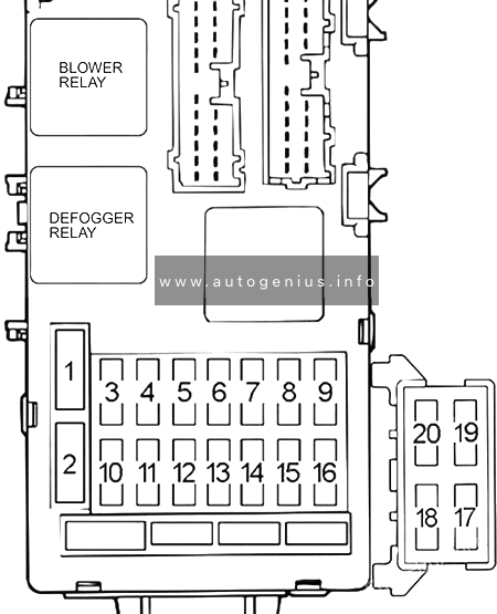
Assignment of the fuses in the passenger compartment
| № | Amps | Load Circuit |
|---|---|---|
| 1 | 30A | Defogger and choke coil |
| 2 | 30A | Automatic compressor controller, resistor and blower motor |
| 3 | 15A | Powertrain control module, ABS-ECU, stoplight, autocruise control-ECU and immobilizer-ECU |
| 4 | – | – |
| 5 | 10A | Powertrain control module, input shaft speed sensor, output shaft speed sensor, backup light, SRS-ECU, and ETACS-ECU |
| 6 | – | – |
| 7 | 15A | Cigarette lighter, accessory socket, remote controlled mirror and multi center display unit |
| 8 | 20A | ETACS-ECU and fuse #20 (Windshield wiper and washer) |
| 9 | 10A | Convertible top control module and ABS-ECU |
| 10 | 10A | Horn, horn relay, theft-alarm horn and theft-alarm horn relay |
| 11 | 15A | Data link connector, ETACS-ECU and combination meter |
| 12 | 10A | Motor antenna assembly (ECLIPSE SPYDER) |
| 13 | 10A | Combination meter, ETACS-ECU, SRS-ECU, auto-cruise control-ECU, column-ECU, multi center display unit and vehicle speed sensor |
| 14 | – | – |
| 15 | – | – |
| 16 | 10A | Blower relay, outside/inside air selection damper control motor, defogger relay, A/C switch, front-ECU, A/C compressor relay and automatic compressor controller |
| 17 | 20A | Audio system (Vehicles with amplifier) |
| 18 | – | – |
| 19 | 20A | Sunroof (ECLIPSE) |
| 20 | 20A | Windshield wiper and washer |
Engine compartment fuse box
Fuse Box Diagram
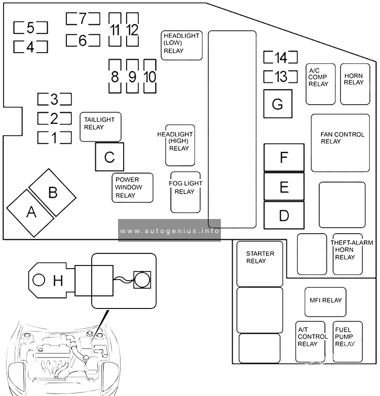
Assignment of the fuses in the engine compartment
| № | Amps | Load Circuit |
|---|---|---|
| 1 | – | – |
| 2 | 15A | Fog light |
| 3 | 10A | Air conditioning system |
| 4 | 10A | ECU power supply, dome light, trunk light, universal garage door opener, sunroof assembly, luggage compartment light, audio system, multi-center display, meter and gauge |
| 5 | 10A | Audio system |
| 6 | 10A | Headlight and theft-alarm system |
| 7 | 10A | Headlight and theft-alarm system |
| 8 | 10A | Rheostat, taillight, position light, rear side marker light and illumination circuit |
| 9 | 10A | Taillight, position light, rear side marker light and license plate light |
| 10 | – | – |
| 11 | 10A | Headlight |
| 12 | 10A | Headlight |
| 13 | 20A | INVECS-II 4A/T, MFI system, air conditioning system, cooling system and immobilizer system |
| 14 | 10A | Charging system, central door locking system (Vehicles with keyless entry system), turn-signal light and hazard warning light |
| A | 60A | Instrument panel fuses №1, 2, 3, 10, 11 |
| B | – | – |
| C | 30A | Instrument panel fuses №17, 19, power windows, power seat, convertible top and audio system (Vehicles with amplifier) |
| D | 50A | Air conditioning system and cooling system |
| E | 50A | Anti-lock braking system |
| F | 30A | Convertible top circuit |
| G | 30A | Ignition switch circuit |
| H | 120A | Generator circuit (the fusible link is located on the battery) |
WARNING: Terminal and harness assignments for individual connectors will vary depending on vehicle equipment level, model, and market.