Mitsubishi FTO (1997 – 2000) – fuse and relay box diagram
Year of production: 1997, 1998,1999, 2000
The Mitsubishi FTO (DE), a 2-door coupe, was manufactured from 1994 to 2000. This article provides fuse box diagrams for the 1997, 1998, 1999, and 2000 models, details the locations of the fuse panels inside the vehicle, and outlines the function of each fuse (fuse layout)
Passenger compartment fuse box
Fuse Box Location
The fuses are located below the instrument panel.
Fuse Box Diagram
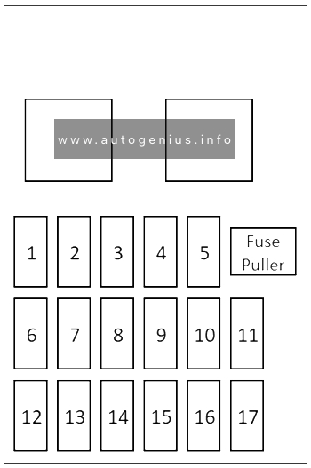
Assignment of the fuses in the passenger compartment
| № | Amps | Load circuit |
|---|---|---|
| 1 | 15A | Door lock-ECU |
| 2 | 10A | TCL-ECU |
| 3 | 10A | A/T-ECU, A/T indicator lamp, output/input shaft speed sensor, back-up lamp, buzzer-ECU |
| 4 | 10A | SRS-ECU, turn-signal and hazard flasher unit |
| 5 | – | – |
| 6 | 30A | Defogger |
| 7 | – | – |
| 8 | 10A | SRS-ECU, combination meter, sunroof-ECU, vehicle speed sensor, steering wheel sensor (vehicles with TCL), buzzer-ECU, motor antenna assembly, voltmeter |
| 9 | 15A | Windshield intermittent wiper relay, windshield wiper motor, remote-controlled mirror, rear intermittent wiper relay, rear washer motor, rear wiper motor |
| 10 | – | – |
| 11 | 30A | Blower motor |
| 12 | 10A | Horn |
| 13 | 10A | A/C-ECU, ABS-ECU, ABS valve relay, defogger relay, power window relay, blower high speed relay, blower motor relay |
| 14 | 15A | Cigarette lighter |
| 15 | 10A | – |
| 16 | 10A | – |
| 17 | 20A | Sunroof-ECU |
Engine compartment fuse box
Fuse Box Diagram
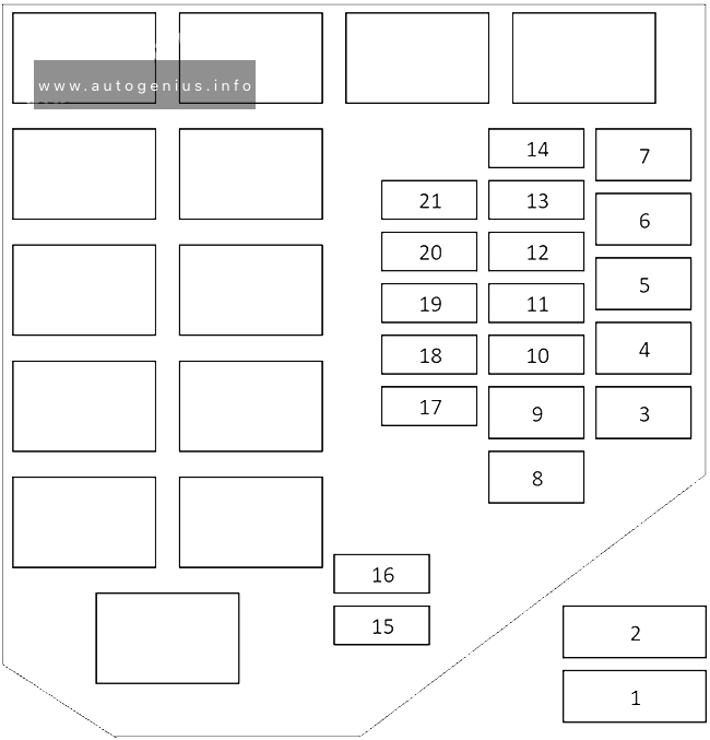
Assignment of the fuses in the engine compartment
| № | Amps | Circuit |
|---|---|---|
| 1 | 60A | Fuses №16, 17, instrument panel fuses №1, 6, 11 |
| 2 | 100A | Fusible link № 1, 8, 9, fuse №10 (when engine stops); Fusible link №3, 4, 5, 6, fuses №12, 13, 14 (when engine starts) |
| 3 | 20A | INVECS-II 5A/T, TCL, engine control |
| 4 | 40A | Fuse №19, charging, headlamp |
| 5 | 30A | Full-auto air conditioner, cooling |
| 6 | 40A | Ignition switch |
| 7 | – | – |
| 8 | 50A | ABS |
| 9 | 30A | Instrument panel fuses №16, 17, power window |
| 10 | 30A | Condenser fan |
| 11 | – | – |
| 12 | 15A | Fog lamp |
| 13 | 10A | Turn-signal and hazard warning lamp |
| 14 | 15A | Stop lamp |
| 15 | 15A | Keyless entry receiver, motor antenna assembly, spare connector for radio |
| 16 | 10A | A/C-ECU power supply, TCL-ECU power supply, MUT-II power supply, engine-ECU power supply, key cylinder illumination lamp, keyless entry receiver, speedometer, trunk room lamp, clock, door-ajar indicator lamp, buzzer-ECU power supply, map lamp, motor antenna assembly, spare connector for radio |
| 17 | 10A | A/C compressor |
| 18 | 10A | High beam indicator lamp |
| 19 | 10A | Illumination lamp, tail lamp, position lamp, license plate lamp, buzzer-ECU |
| 20 | 20A | Headlamp (LH), fuse №18 (high beam indicator lamp) |
| 21 | 20A | Headlamp (RH) |
WARNING: Terminal and harness assignments for individual connectors will vary depending on vehicle equipment level, model, and market.