AMC Concord (1978 – 1983) – fuse box diagram
Year of production: 1978, 1979, 1980, 1981, 1982, 1983
This article covers the second-generation AMC Concorde, produced from 1978 to 1983. It includes fuse box diagrams for the 1978, 1979, 1980, 1981, 1982 and 1983 models, provides details on the location of the fuse panels inside the vehicle, and explains the function and layout of each fuse.
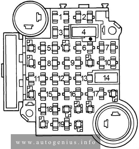
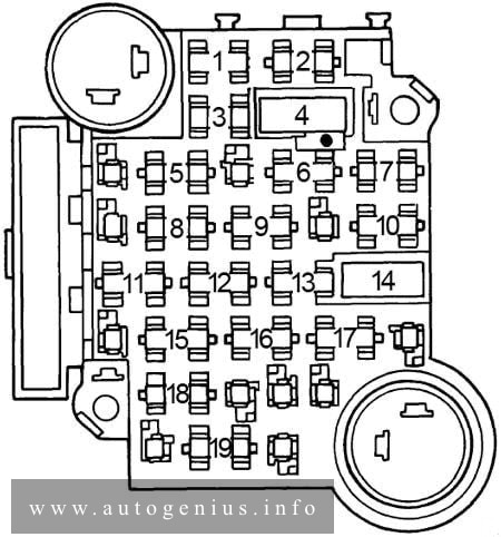
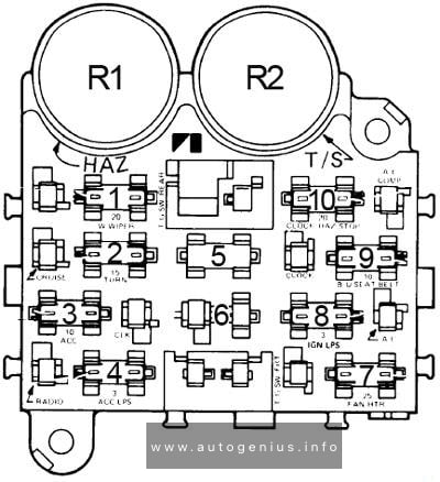
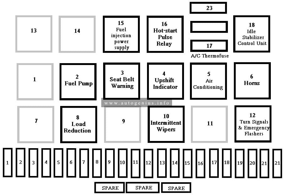
Fuse box diagram
Assignment of the fuses in the fuse box
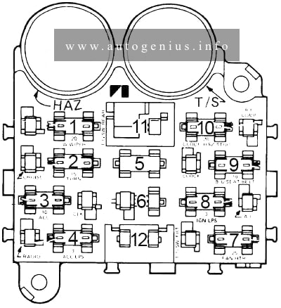
| No. |
A |
Protected Component |
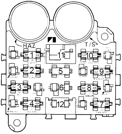
| 1 | 10 | Parking lights, key/headlights warning buzzer |
| 2 | 15 | Stop light and hazard warning |
| 3 | – | – |
| 4 | 3 | Cluster illumination |
| 5 | – | – |
| 6 | – | – |
| 7 | 25 | Heater/blower motor, A/C clutch |
| 8 | 15 | Radio, cigar lighter |
| 9 | 15 | Turn signals, backup lights, windshield washers |
| 10 | 5 | Gauges, seat belt warning |
| 11 | 30 | Power door lock, power windows circuit breaker |
| 12 | 25 | Heated rear window |
Circuit Breaker:
|
||
WARNING: Terminal and harness assignments for individual connectors will vary depending on vehicle equipment level, model, and market.