Alfa Romeo 164 (1988 – 1997) – fuse box diagram
Year of production: 1988, 1989, 1990, 1991, 1992, 1992, 1993, 1994, 1995, 1996, 1997
Alfa Romeo 164 is a business class car manufactured by Alfa Romeo. Produced from 1987 to 1998 in the sedan body. This material is suitable for cars produced in 1988, 1989, 1990, 1991, 1992, 1993, 1994, 1995, 1996, 1997 for finding and replacing fuses and relays on Alfa Romeo 164 cars. We will also show the fuse box diagrams and their locations, as well as the purpose of their elements.
Passenger compartment
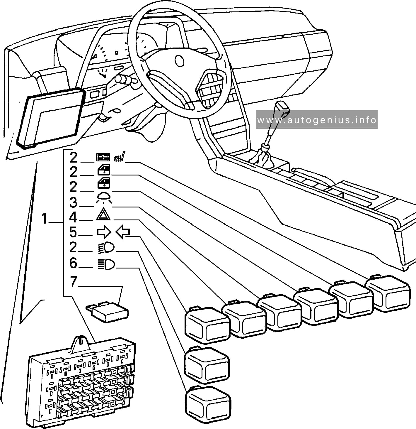
Fuse box location
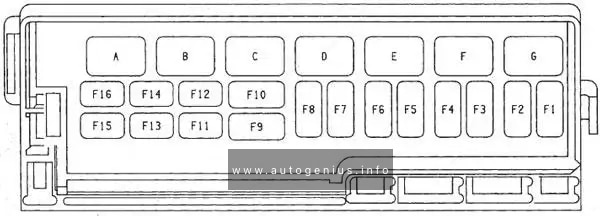
Fuse and relay box is locate under the dashboard
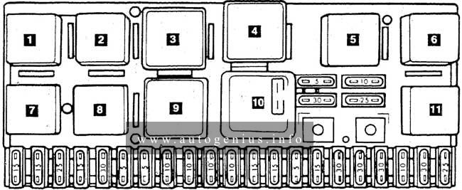
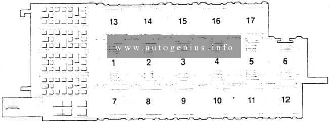
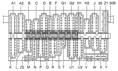
Fuse box diagram
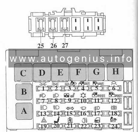
| Relays | A | Description |
| A | Headlamp high beam relay | |
| B | Headlamp low beam relay | |
| C | Turn Signal / Hazard Relay | |
| D | Front / Rear Lamp Relays | |
| E | Interior lamp relay | |
| F | Front power window relay | |
| G | Rear power window relay | |
| H | Seat heater / sunroof relay | |
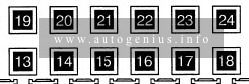
| 1 | 10 | LH side lamp, LH tail lamp, license plate lamp, cigarette lighter lamp |
| 2 | 10 | LH lamp, RH lamp, Tailgate lamp, instrument cluster illumination, vanity mirror lamp |
| 3 | 20 | Heated door mirrors, heated rear window, heated windscreen, cigarette lighter – front |
| 4 | 30 | Power window regulator – front left |
| 5 | 30 | Power window regulator – front right |
| 6 | 10 | Interior lamp |
| 7 | 10 | Low beam headlamp – LH |
| 8 | 10 | Low beam headlamp – right |
| 9 | 20 | Sunroof, seat heater |
| 10 | 10 | Cluster illumination rheostat, A / C relay, A / C compressor clutch relay |
| 11 | 30 | Power window regulator – rear right |
| 12 | 30 | Power window regulator – rear left |
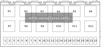
| 13 | 10 | High beam headlamp – LH |
| 14 | 10 | High beam headlamp – right |
| 15 | 10 | Direction indicators, front / rear lamps |
| 16 | 20 | Reversing lights, windshield wiper |
| 17 | 15 | Fog lights-front |
| 18 | 10 | Stop lights |
| 19 | 20 | Headlamp washer, hazard warning lights |
| 20 | 30 | Power seat |
| 21 | 10 | Cooling fan motor relay, glow plug relay, fuel heater relay, cruise control |
| 22 | 10 | Rear fog lamps |
| 23 | 15 | Central locking |
| 24 | 10 | Cigar lighter , rear |
| 25 | 75 | “+” battery |
| 26 | 10 | Power supply circuit |
| 27 | 30 | Fuel filler flap / cover |
| 28 | 3 | A / C compressor magnetic clutch |
| 29 | 75 | Anti-theft system |
| The fuse number 24, 10A, is responsible for the cigarette lighter. | ||
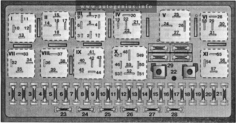
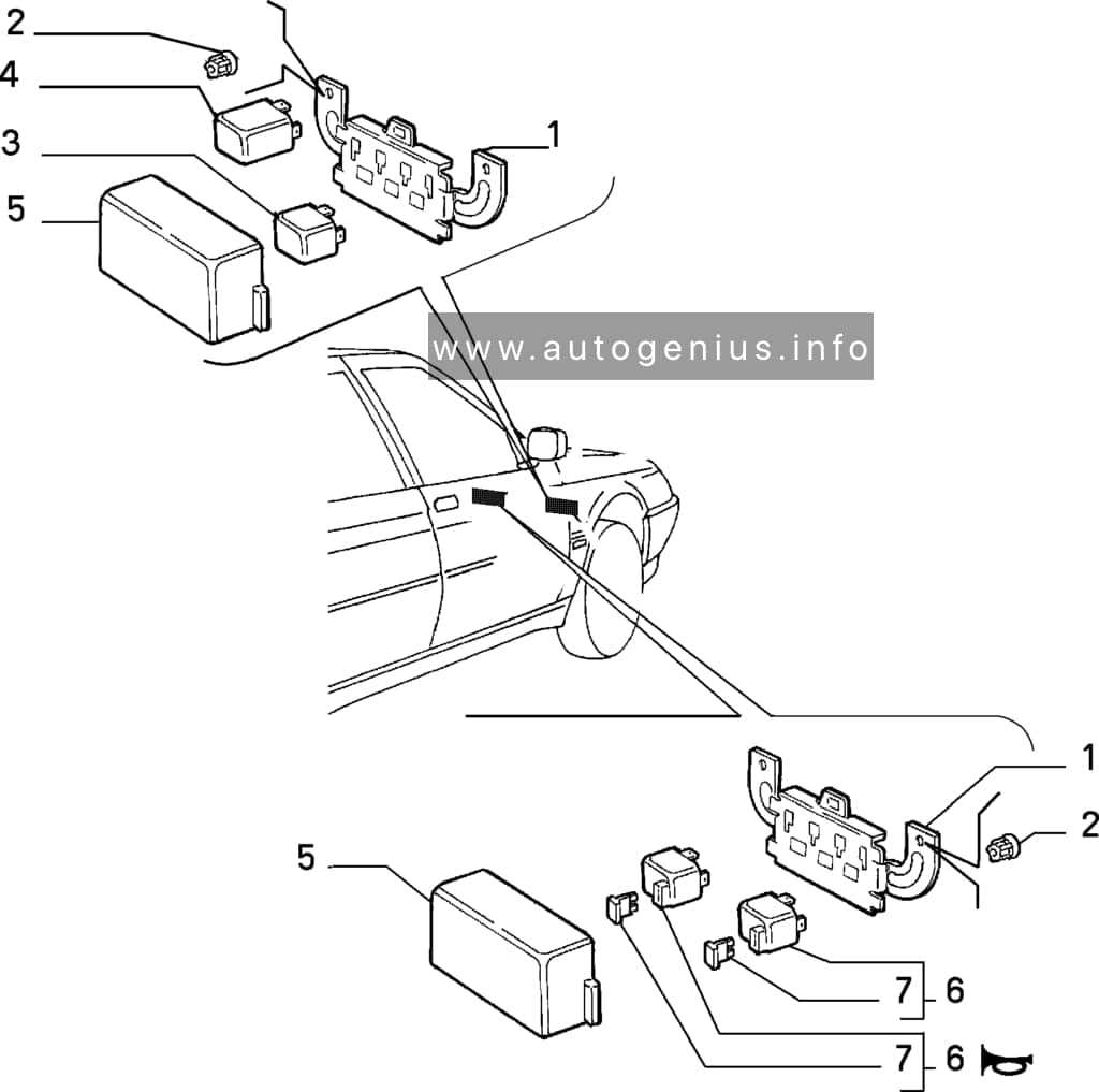
Engine compartment
Fuse and relay boxes
There are several small boxes with relays and fuses under the hood.
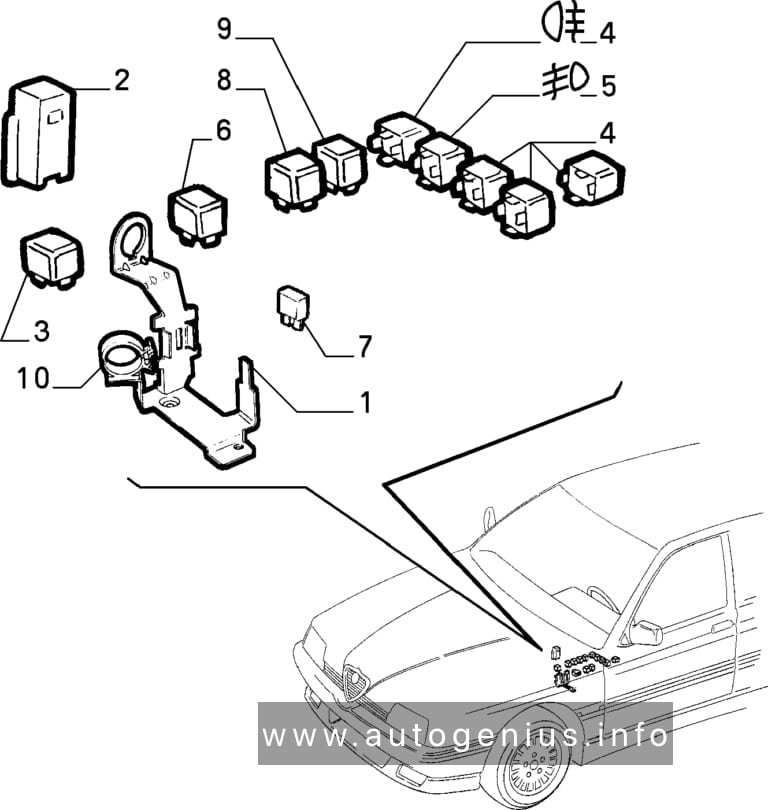
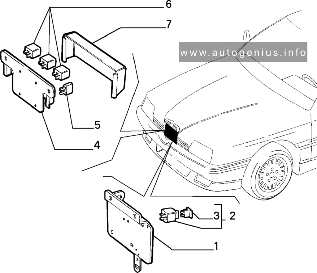
| No. | A | Description |
| 1 | Common relay | |
| 2 | Relay of fuel pump | |
| 3 | Relay of device of the variable valve timing system | |
| 4 | Relay 2 of the electronic engine color unit | |
| 1 | 15 | Fuel pump |
| 2 | 3 | Electronic engine control unit |
| 3 | 75 | Oxygen sensor |
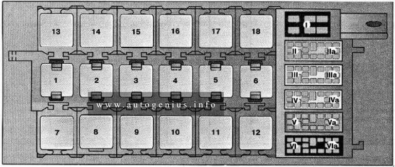
Luggage compartment fuse box
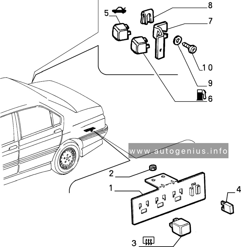
| Description | |
| Suspension control relay | |
| Heated rear window relay | |
| Rear seat motor relay | |
| 10A | Anti-thef system |
| 3A | Anti-thef alarm horn |
| 10A | Phone |
| 40A | Heated rear window |
WARNING: Terminal and harness assignments for individual connectors will vary depending on vehicle equipment level, model, and market.