Mazda Miata (1989 – 1997) – fuse and relay box diagram
Year of production: 1989, 1990, 1991, 1992, 1993, 1994, 1995, 1996, 1997
This article covers the first-generation Mazda MX-5 Miata (NA), produced between 1989 and 1997. It includes fuse box diagrams for the 1989–1997 models, provides details on the locations of the fuse panels inside the vehicle, and explains the function and layout of each fuse and relay.
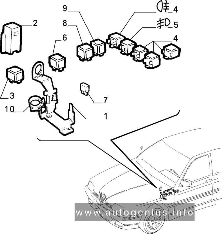
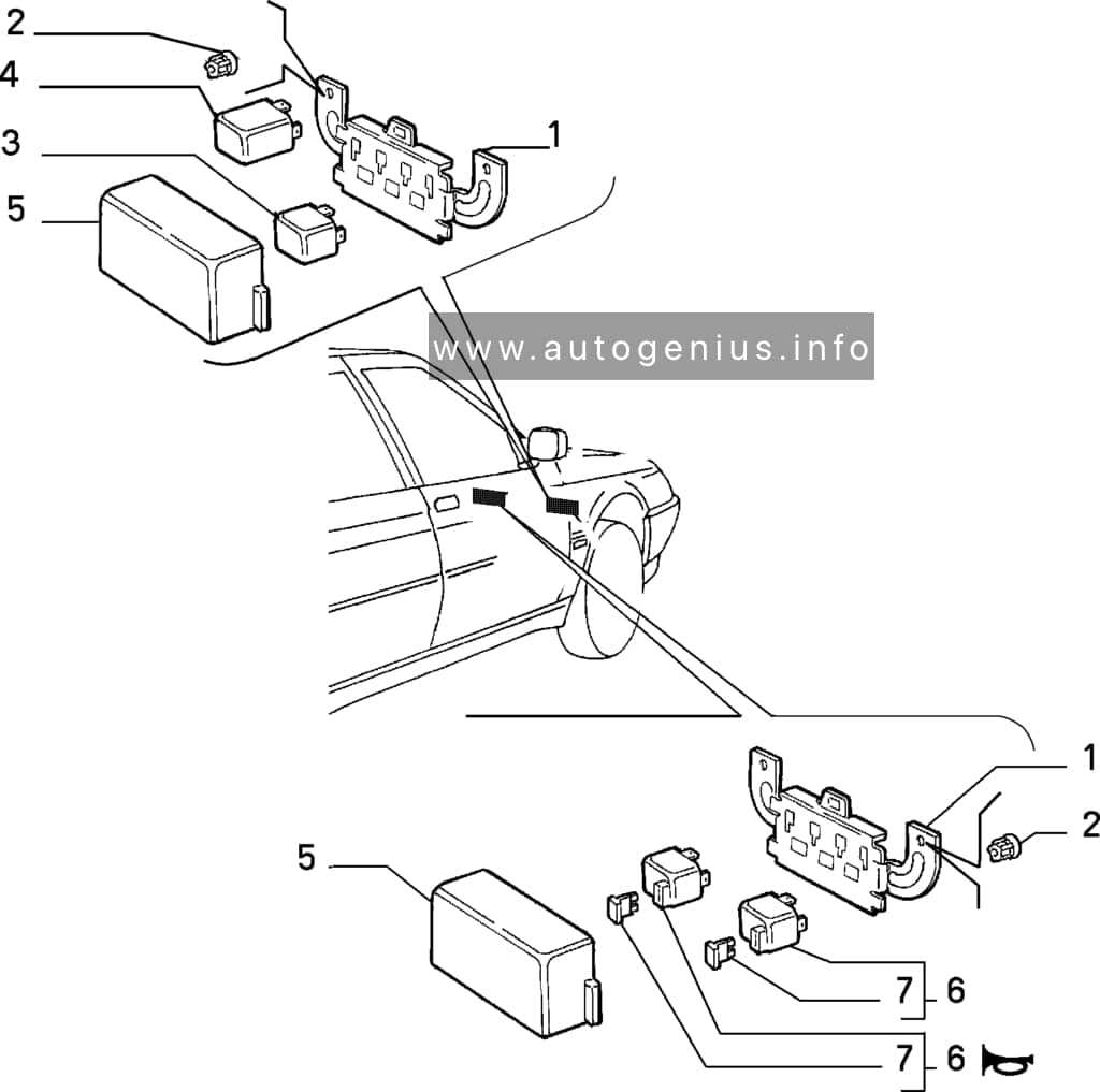
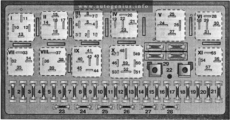
Engine compartment
Fuse Box Location
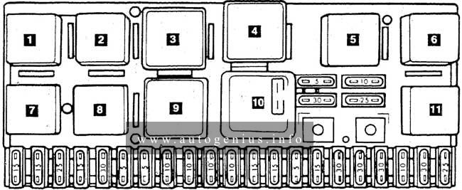
Fuse Box Diagram
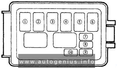
Assignment of the fuses in the engine compartment
| Position | Name | Fuse rating [A] | Description |
| 1 | HEAD | 30 | Headlights |
| 2 | INJ | 30 | Fuel injection, Alternator |
| 3 | MAIN | 80 | For protection of all circuits |
| 4 | BTN | 40 | Refer to HAZARD (15A), STOP (15A), ROOM (10A), TAIL (15A) |
| 5 | ABS | 60 | Antilock brake system |
| 6 | COIOLING FAN | 30 | Cooling fan |
| 7 | AIR BAG | 10 | Air bag |
| 8 | AD FAN | 20 | Additional fan (Air conditioner) |
| 9 | ST SIG | 10 | Fuel injection |
| 10 | RETRACTOR | 30 | Headlight retractor |
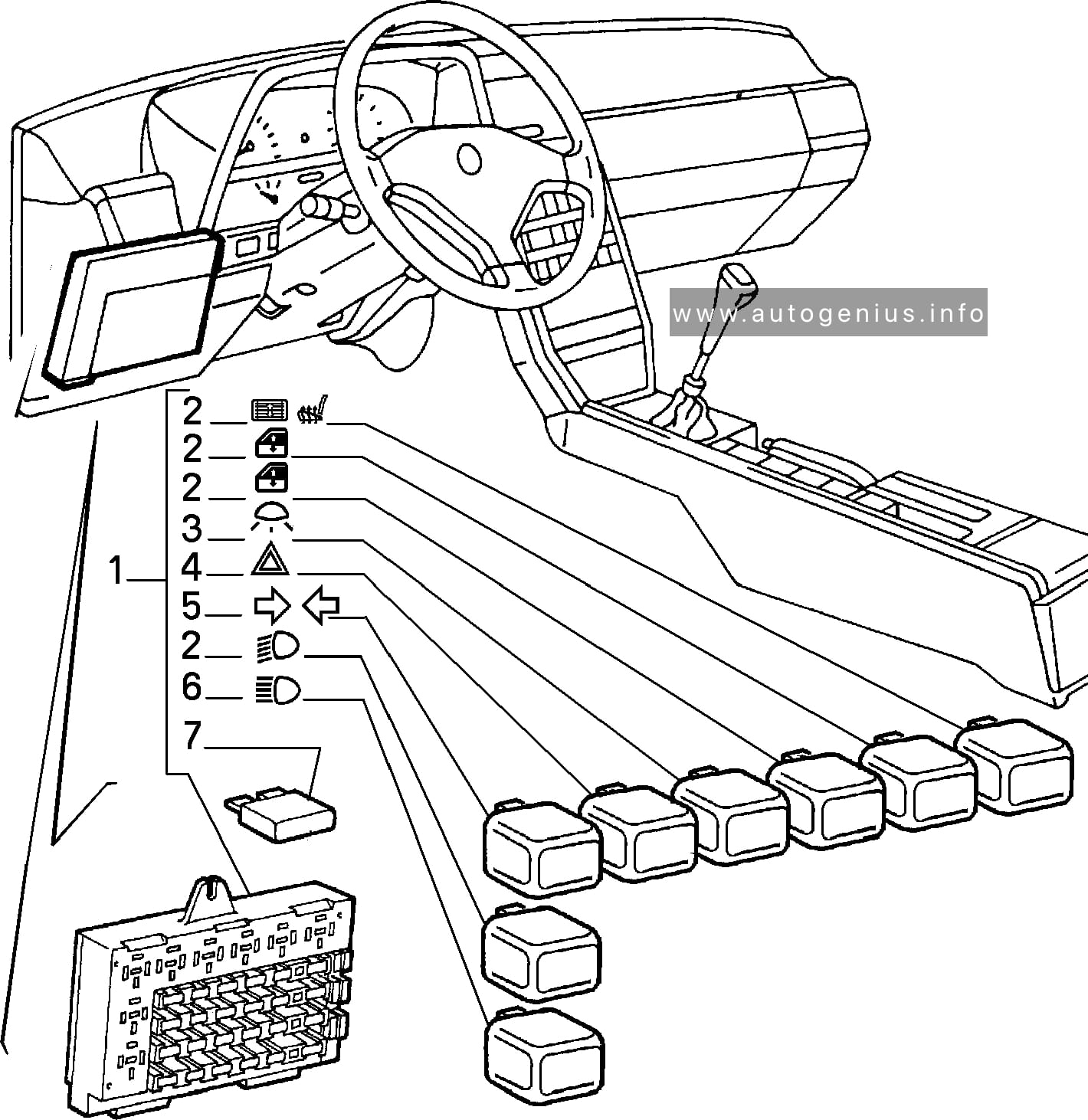
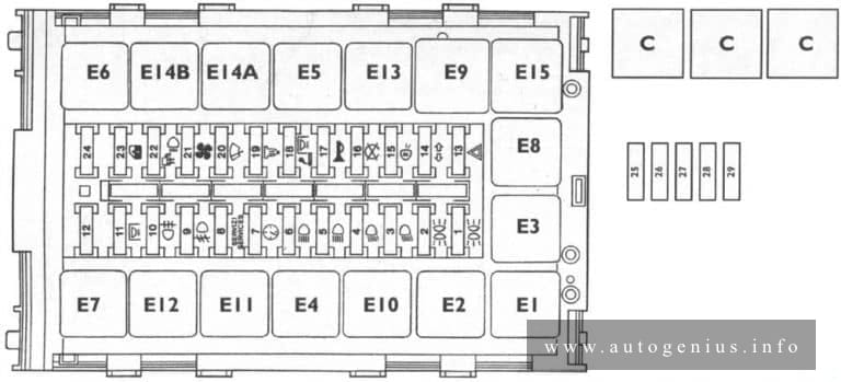
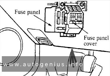
Passenger compartment
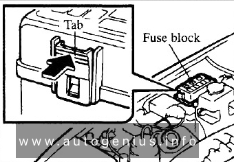
Fuse Box Location
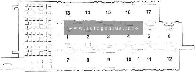
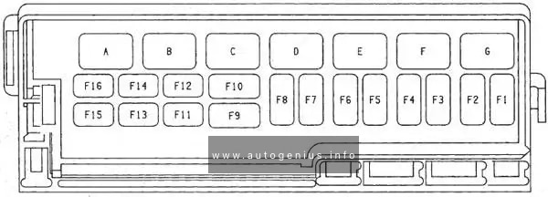
Fuse Box Diagram
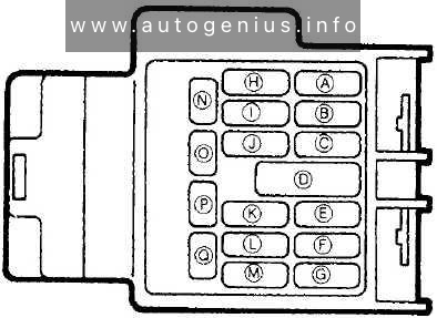
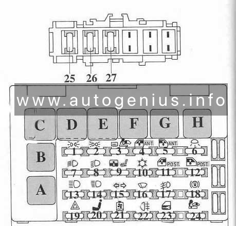
Assignment of the fuses in the passenger compartment
| Position | Name | Fuse rating [A] | Protected component |
| A | ENGINE | 15 | Cooling fan |
| B | METER | 10 | Gauges, Warning lights, Turn-signal lights, Cruise control |
| C | AIR BAG | 15 | Air bag |
| D | HEATER | 30 | Heater |
| E | — | — | — |
| F | POWER WIND | 30 | Power windows |
| G | WIPER | 20 | Wipers, Washer |
| H | — | — | — |
| I | TAIL | 15 | Tail lights |
| J | — | — | — |
| K | STOP | 15 | Shift lock, Cruise control, Horn, Stoplights |
| L | HAZARD | 15 | Hazard warning lights |
| M | — | — | — |
| N | ROOM | 10 | Interior lamps, Warning buzzers, Radio/cassette and compact disc player and clock |
| O | CIGAR | 15 | Radio/cassette and compact disc player and clock, Cigarette lighter |
| P | — | — | — |
| Q | — | — | — |
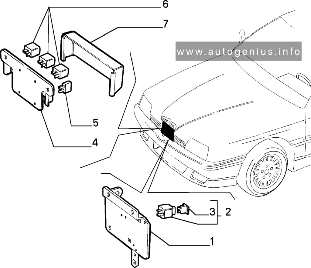
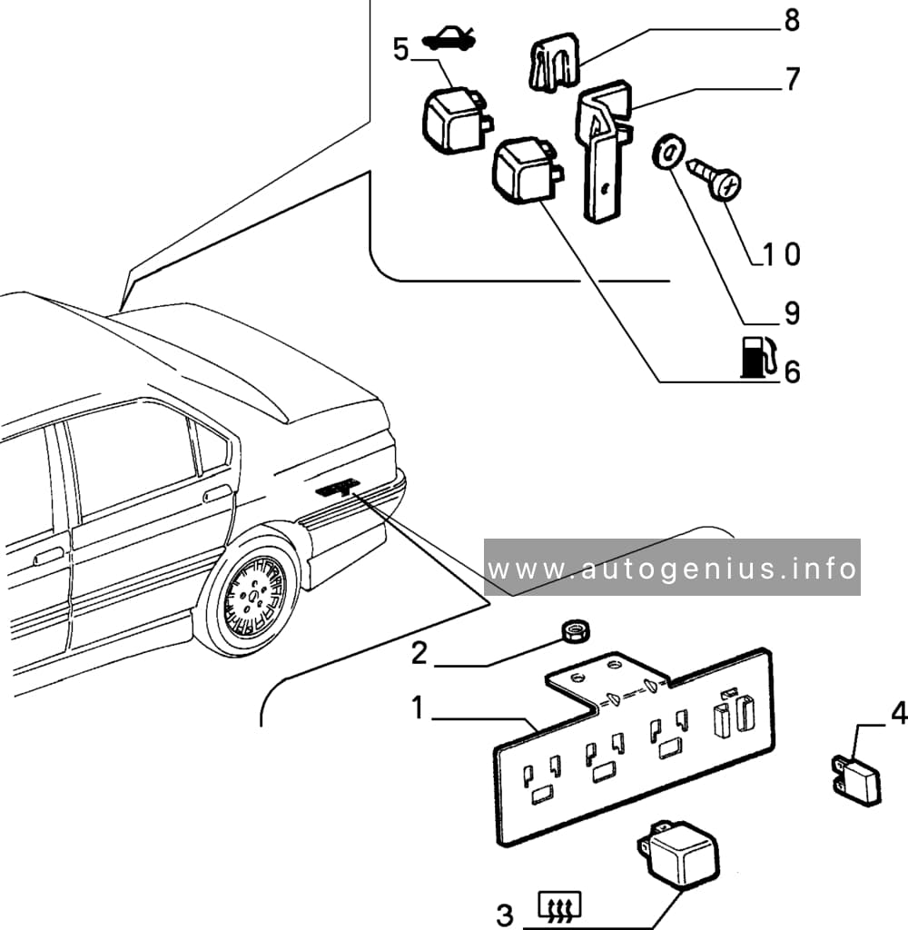
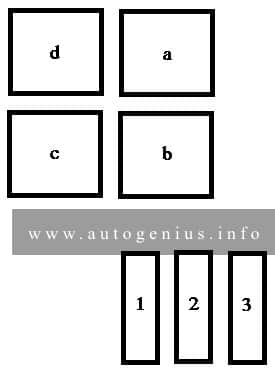
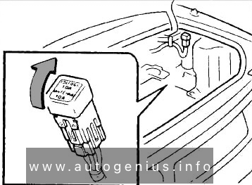
Luggage compartment
Fuse Box Location
Fuse Box Diagram
Assignment of the fuses in the trunk
| Number | Name | Ampere ratting [A] | Description |
| 1 | DEFOG | 10 | Rear defroster |
| 2 | ANTENNA | 10 | Auto antenna |
WARNING: Terminal and harness assignments for individual connectors will vary depending on vehicle equipment level, model, and market.