Iveco Daily (1989 – 2000) – fuse and relay box diagram
Year of production: 1989, 1990, 1991, 1992, 1993, 1994, 1995, 1996, 1997, 1998, 1999, 2000
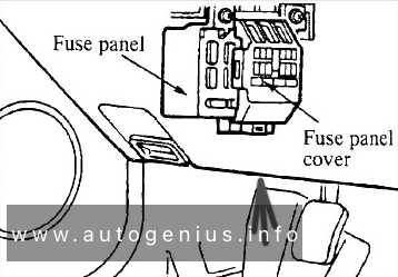
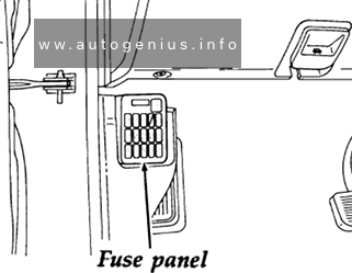
This article covers the second-generation Iveco Daily II (2nd generation), produced from 1989 to 2000. It includes fuse box diagrams for the 1989, 1990, 1991, 1992, 1993, 1994, 1995, 1996, 1997, 1998, 1999 and 2000 models, provides details on the location of the fuse panels inside the vehicle, and explains the function and layout of each fuse.
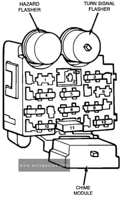
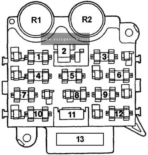
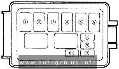
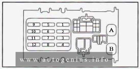
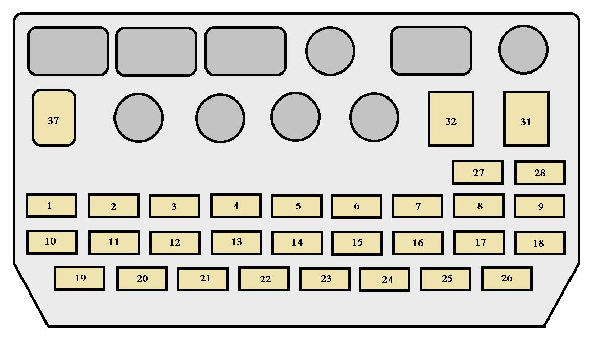
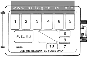
Fuse box diagram
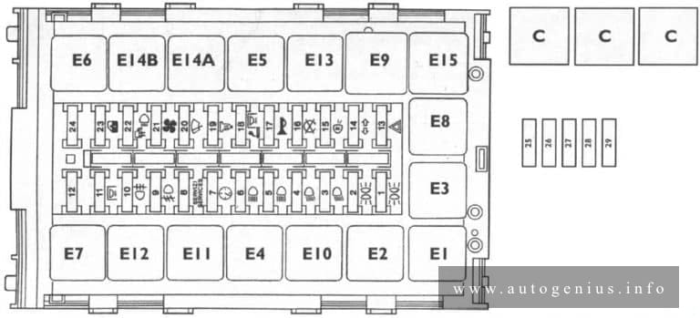
Assignment of the fuses in the fuse box
| No. | A | Function |
| 1 | 5 | Lh front parking light – Lh number plate light- Rh rear parking light – Rh front and Lh rear marker |
| 2 | 5 | lights – Dashboard. Rh front parking light – Rh number plate light -Lh rear parking light – Lh front and Rh rear |
| 3 | 7,5 | marker lights. Lh low beam light |
| 4 | 7,5 | Rh low beam light |
| 5 | 7,5 | Lh high beam light |
| 6 | 7,5 | Rh high beam light |
| 7 | 3 | Electronic speedometer or tachograph |
| 8 | 5 | Brake – instrument – telltale failure |
| 9 | 10 | Fog headlights |
| 10 | 3 | Rear fog lamps |
| 11 | 5 | Interior lighting (bus) |
| 12 | 7,5 | Not used |
| 13 | 10 | Hazard lights |
| И | 5 | Tractor unit turn signal lights |
| 15 | 3 | Engine stop |
| 16 | 7,5 | Reversing lights – stop lights |
| 17 | 10 | Homs |
| 18 | 7,5 | Interior lighting – Cigar lighter |
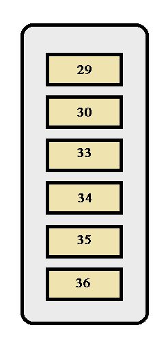
| 19 | 15 | Heated fuel oil filter |
| 20 | 10 | Windscreen wiper – Windscreen washer pump |
| 21 | 15 | Electric heater – Electromagnetic fan |
| 22 | 7,5 | Push switch lighting – flashing light |
| 23 | 25 | Power window – Electromagnetic fan |
| 24 | 10 | Emergency control pushbutton (Bus) |
| 25 | 20 | Air conditioning |
| 26 | 20 | Air conditioning |
| 27 | 25 | Air conditioning |
| 28 | 25 | Electric heater |
| 29 | 40 | Thermostarter control unit |
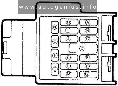
| Relays | ||
| E1 | Low beam lights (switch contacts) | |
| E2 | High beam lights (N.O. contact) | |
| E3 | Users cutoff during starting stage (N.O. contact) | |
| E4 | Fog lamps (switch contacts) | |
| E5 | Heated fuel oil filter | |
| E6 | Emergency control unit | |
| E7 | Day lights + fog lamps | |
| E8 | Horns (N.O. contact) | |
| E9 | Windscreen wiper intermittent | |
| E10 | Flashing light (N.O. contact) | |
| E11 | Diode for emergency control unit (with day lights) | |
| E12 | Not used | |
| E13 | Brake system failure (switch contact) | |
| E14a | Emergency control unit (with day lights) | |
| E14b | Emergency control unit (with day lights) | |
| E15 | Direction indicators – single charge emergency | |
| C | Air conditioning | |
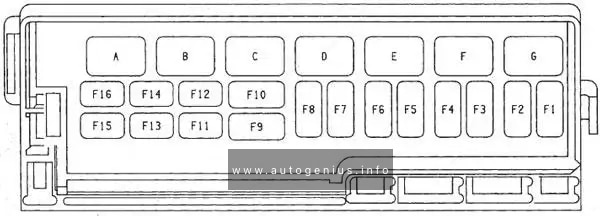
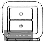
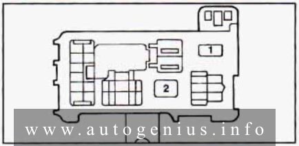
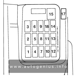
Engine compartment
Fuse box diagram
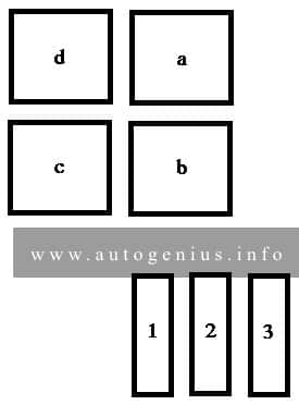
Assignment of the fuses in the engine compartment
| Fuse | Ampere rating [A] | Description |
| 1 | 30 | Electro-hidraulic assembly (Power Pack) |
| 2 | 20 | Electronic control unit (from battery positive) |
| 3 | 20 | Electronic control unit (lock and key protection) |
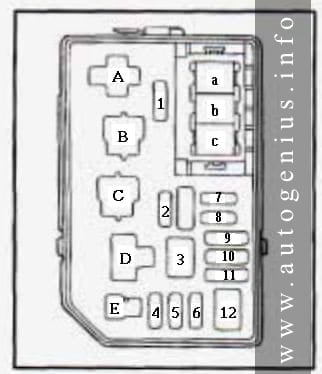
| Relay | Description |
| a | Circuit protection diode casing |
| b | Optical indicator ON button |
| c | Reversing light |
| d | Buzzer (acoustic indicator) |
WARNING: Terminal and harness assignments for individual connectors will vary depending on vehicle equipment level, model, and market.


