Volkswagen Taro (7A; 1990 – 1997) – fuse and relay box diagram
Years of production: 1990, 1991, 1992, 1993, 1994, 1995, 1996, 1997
The Volkswagen Taro, a pickup truck, was produced from 1989 to 1997. This article includes fuse box diagrams for the 1990 through 1997 models, provides details on the locations of the fuse panels inside the vehicle, and explains the function of each fuse and relay (fuse layout).
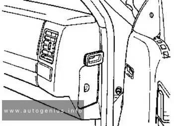
Fuse Box Location
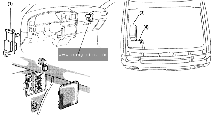
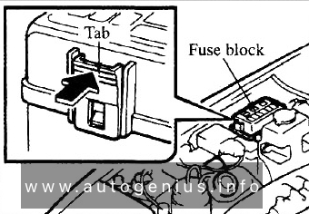
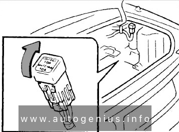
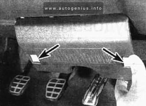
- Fuse box (passenger compartment)
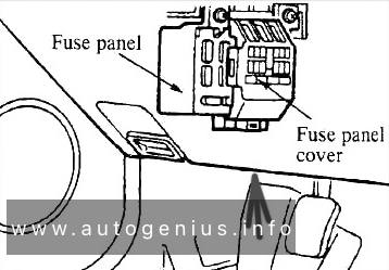
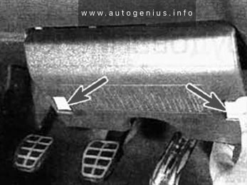
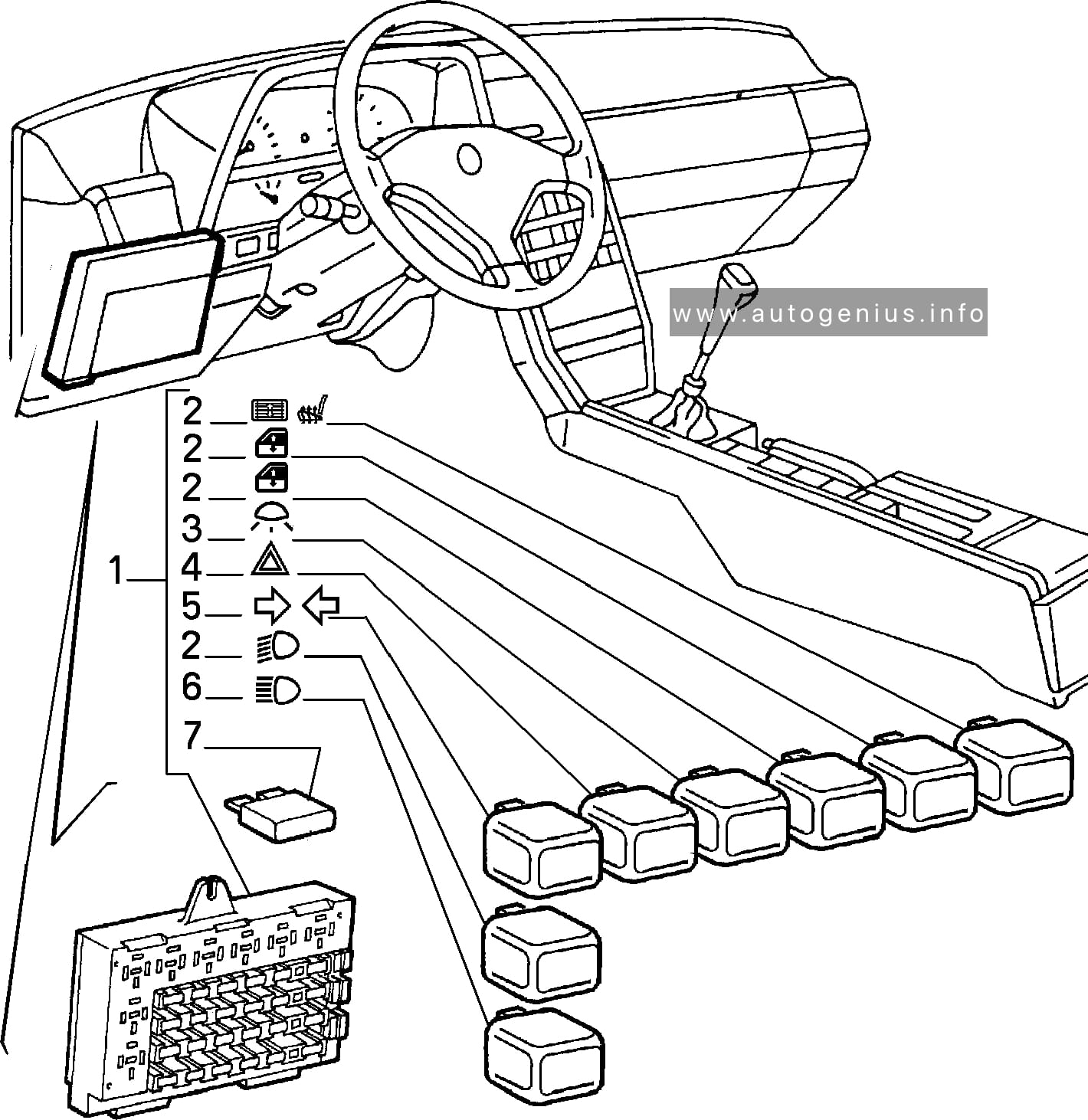
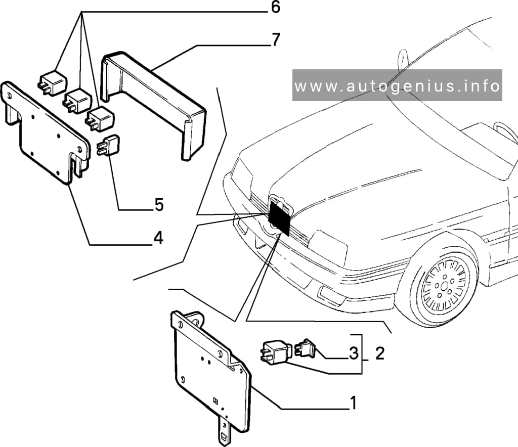
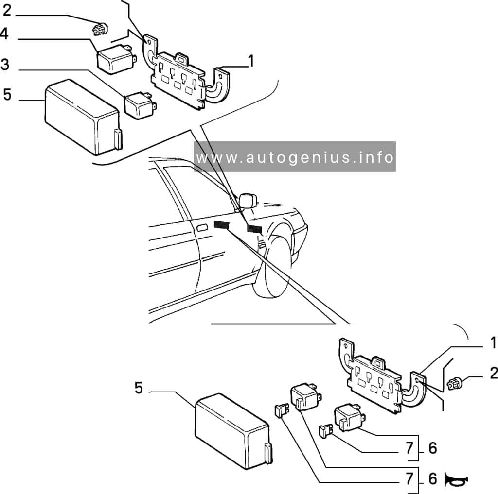
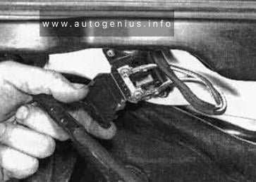
The fuse panel is located on the left side of the car, behind the lid below the dashboard. - Relay block
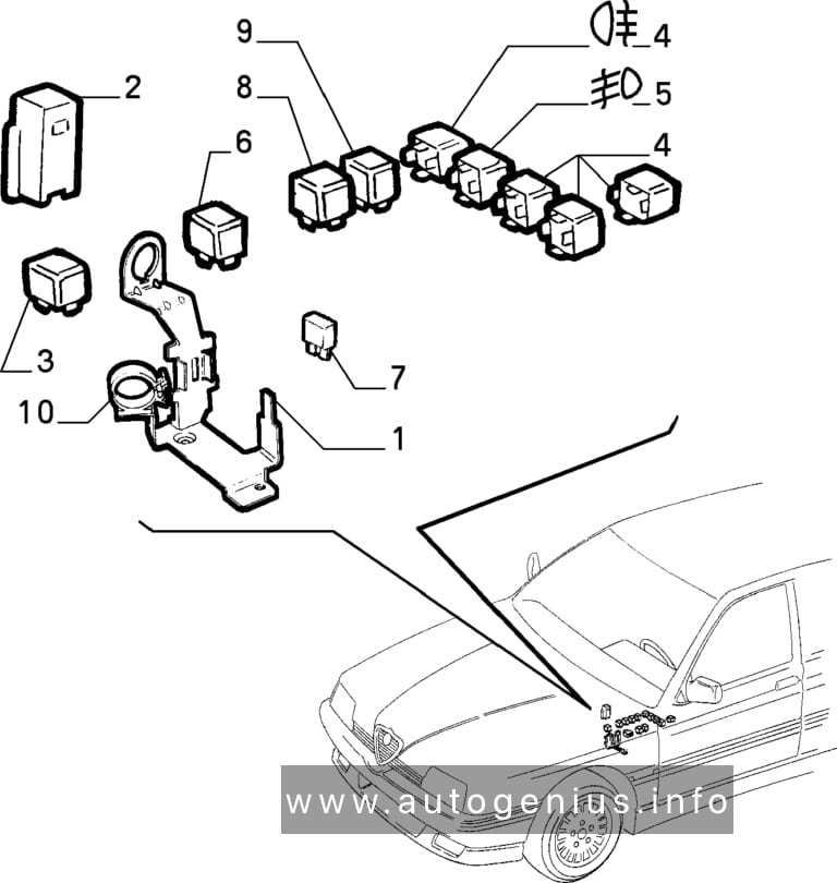
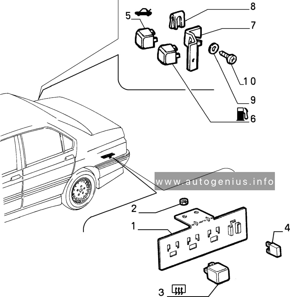
- Fuse box (engine compartment)
- Main fuse (FL MAIN)
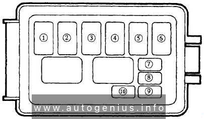
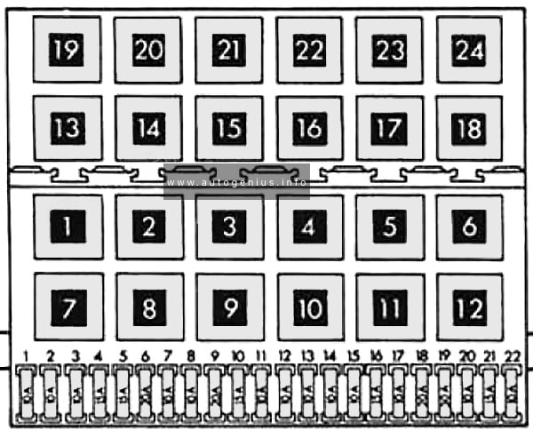
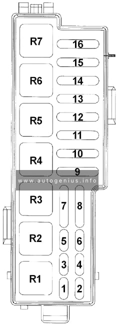
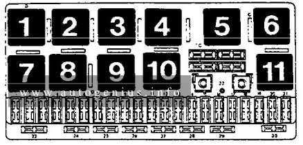
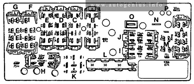
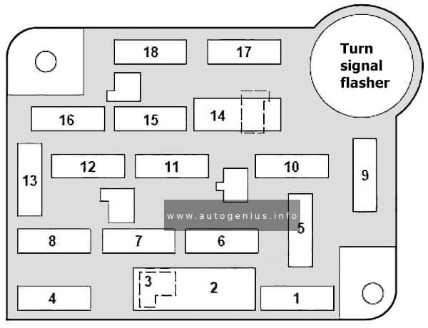
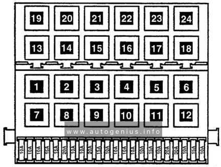
Passenger Compartment Fuse Box
Fuse Box Diagram
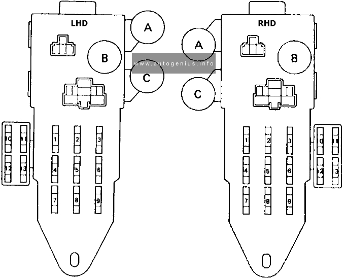
Assignment of the fuses in the passenger compartment
| No. | A | Protected components |
| 1 | 10A | ENGINE: Main relay, Cruise control ECU |
| 2 | 7.5A | IGN: EFI main relay, O/D indicator light, Pattern select switch, Oil temp. select switch |
| 3 | 10A | REAR: Taillight, Integration relay, Light reminder relay, Daytime running light relay |
| 4 | 20A | WIPER: Washer / Wiper |
| 5 | 10A | GAUGE: Combination meter, Antenna, Cruise control ECU, Cruise control indicator light, Brake warning light, Parking brake warning switch, brake fluid level warning switch, Door lock control relay, Integration relay, Light reminder relay, Daytime running light relay |
| 6 | 10A/15A | STOP: Stop light, Stop light switch, Cruise control ECU |
| 7 | 7.5A | RADIO: Radio, Mirror switch, Light reminder relay |
| 8 | 15A | CIG: Cigarette lighter, Integration relay |
| 9 | 10A | TURN: Turn signals, Integration relay |
| 10 | 15A | REAR ANTI LOCK: Rear anti lock |
| 11 | – | – |
| 12 | 15A | DEMIST: Demister |
| 13 | – | – |
| A | Rear Fog light Relay (U.K.) | |
| B | Rearlight Control Relay | |
| C | Demister Relay |
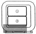
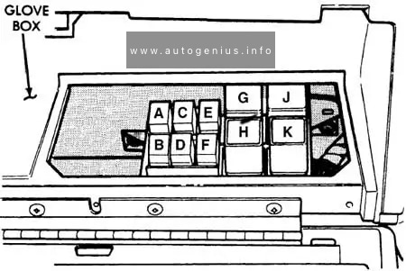
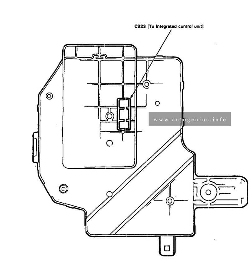
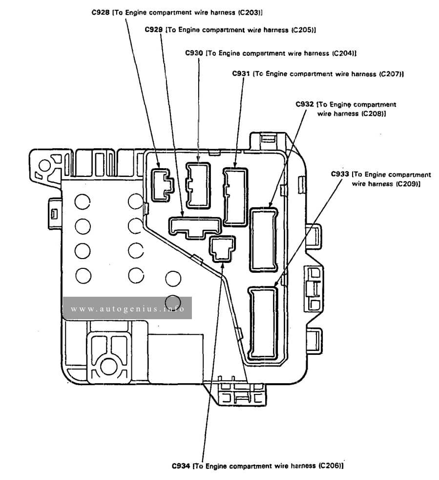
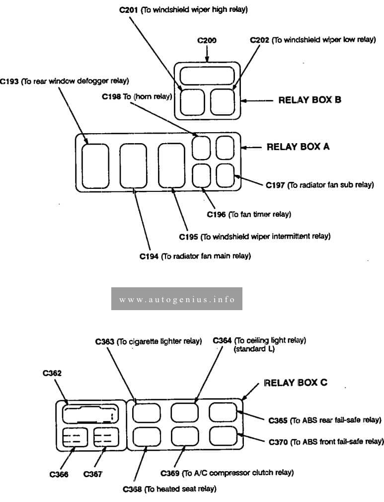
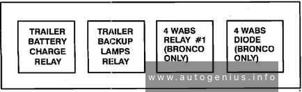
Relay block
Fuse Box Diagram

Assignment of the fuses in the relay block
| No. | A | Protected components |
| 1 | 10A | Air conditioner |
| 2 | 30A | Heater |
| A | Heater Relay |
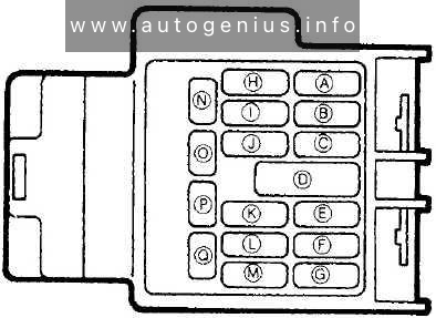
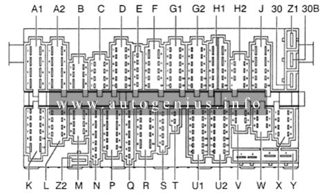
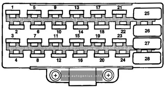
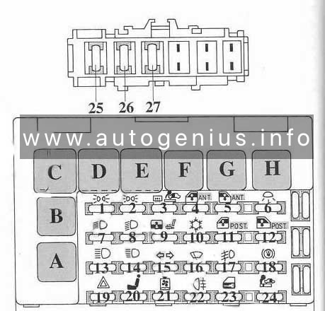
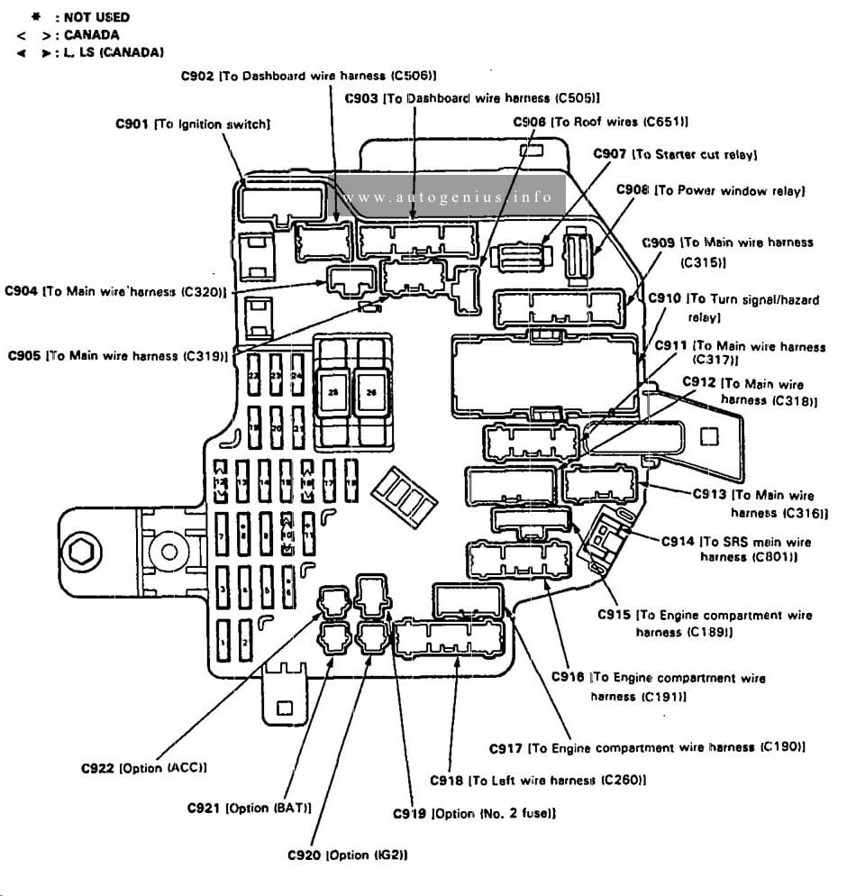
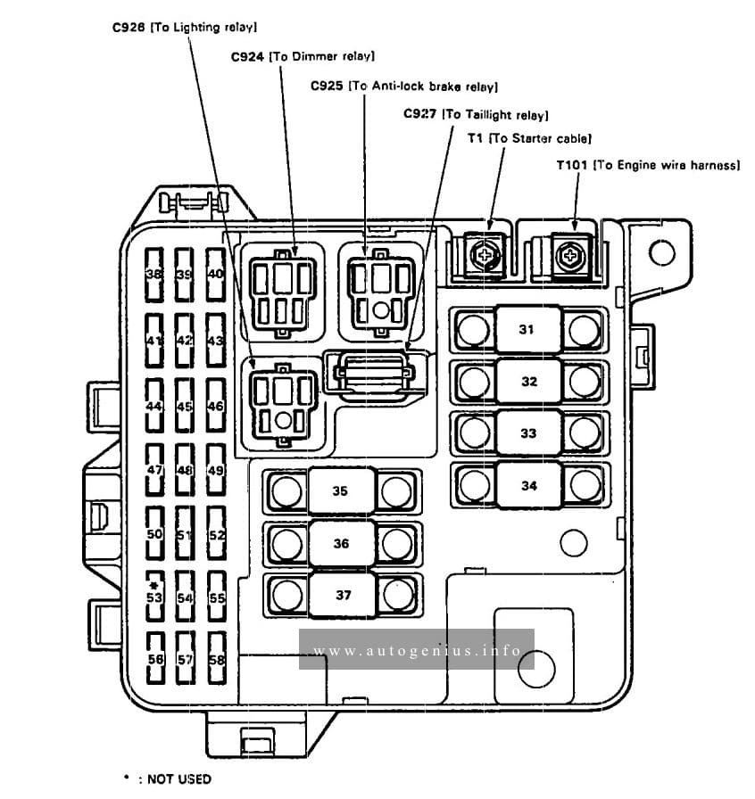
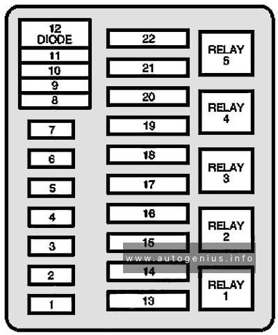
Engine Compartment Fuse Box
Fuse Box Diagram
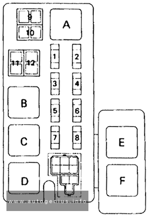
Assignment of the fuses in the engine compartment
| No. | A | Protected components |
| 1 | 7.5A | CHARGE / DRL: Charging system / DRL (Daytime Running Light) |
| 2 | 15A | EFI: EFI main relay, ECM |
| 3 | 15A | HAZ-HORN: Hazard lights, Turn signals, Horn |
| 4 | 15A | DOME: Interior lights, Radio, Antenna, Key unlock warning switch, Integration relay |
| 5 | 10A | HEAD (RH) / HEAD (RH-LO): Right-hand headlight / Right-hand headlights (Low-beam) |
| 6 | 10A | HEAD (LH) / HEAD (LH-LO): Left-hand headlight / Left-hand headlights (Low-beam) |
| 7 | 10A | HEAD (RH-HI) / A/C: Right-hand headlight (High-beam) / Air conditioner |
| 8 | 10A | HEAD (LH-HI): Left-hand headlight (High-beam) |
| 9 | 80A | ALT (FL) / GLOW (FL): Alternator (22R-E Engine) Glow plugs (L Series Engine) |
| 10 | 60A/80A | AM1 (FL) / ALT (FL) |
| 11 | 40A/60A | AM1 (FL ): Ignition switch, Starting system, “POWER”, “REAR ANTI LOCK”, “RADIO”, “CIG”, “WIPER”, “TURN”, “ECM-IG”, “ENGINE” fuses |
| 12 | 30A | AM2 (FL): Ignition switch, “IGN”, “MFI” fuses |
| A | 40A | Heater fuse / Dimmer Relay |
| B | Headlight Control Relay | |
| C | EFI Relay (22R-E Engine) Fuel Heater Relay (L Series Engine) |
|
| D | CMH Relay | |
| E | Dim-Dip Relay №2 (U.K.) | |
| F | Dim-Dip Relay №3 (U.K.) |
WARNING: Terminal and harness assignments for individual connectors will vary depending on vehicle equipment level, model, and market.