Volkswagen Crafter I (Type 2E / 2F; 2006 – 2016) – fuse and relay box diagram
Year of production:2006, 2007, 2008, 2009, 2010, 2011, 2012, 2013, 2014, 2015, 2016
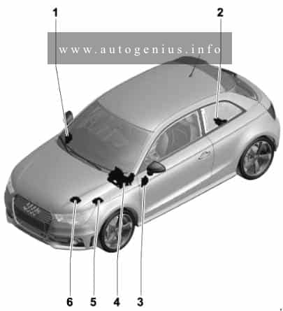
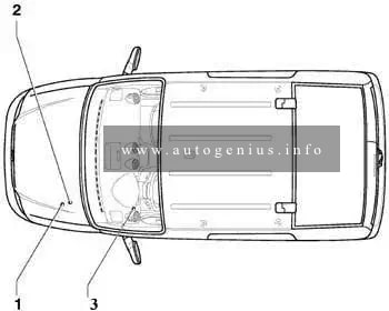
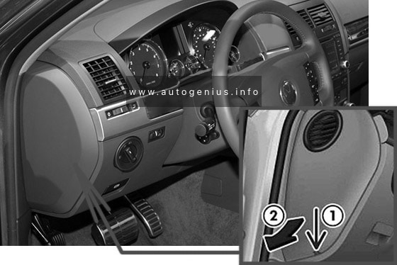
Fuse box location
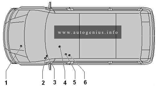
- Terminal 30 voltage supply fuse -S190-
- Fuse holder A -SA- Fuses
- Fuse holder B -SB- Fuses
- Fuse holder C -SC- Fuses
- Fuse holder D -SD- Fuses
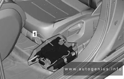
- Single fuses under driver seat
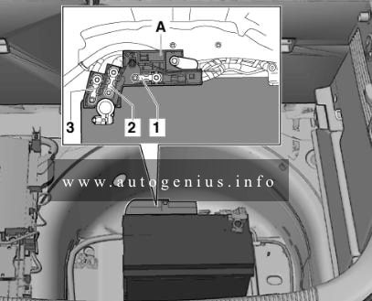
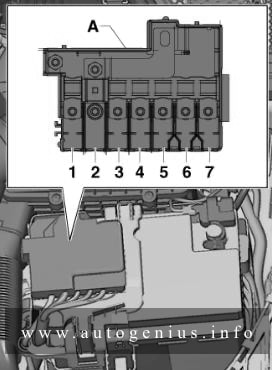
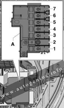
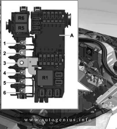
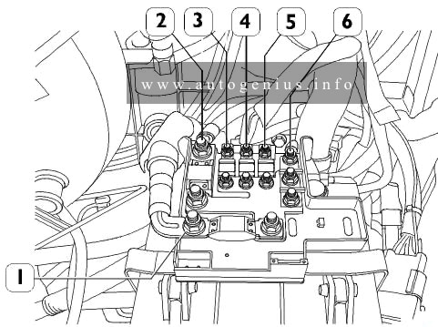
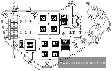
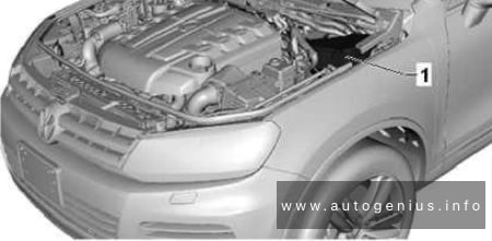
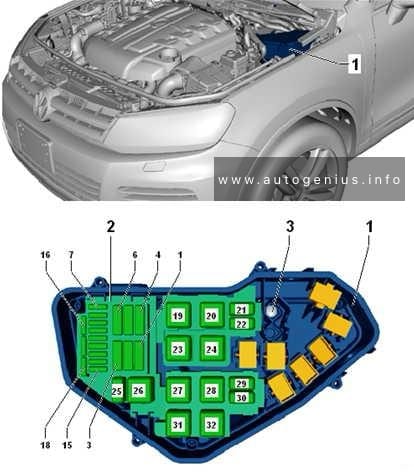
Engine compartment
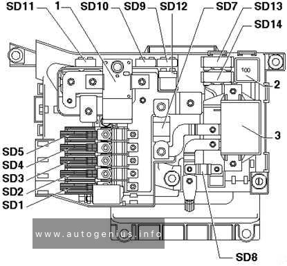
Fuse box diagram (Fuses (SA) on fuse holder, on the battery (2))
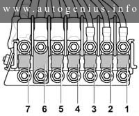
Assignment of the fuses and in the engine compartment (holder SA)
| № | A | Function/component |
| 1 | 80 | Automatic glow period control unit -J179- |
| 2 | 40 60 / 80 |
Radiator fan control unit -J293- (only on models with A/C system) radiator fan -V7- (only on models with A/C system) right radiator fan -V35- (only on models with air conditioning system) |
| 3 | 80 | Onboard supply control unit -J519- Engine component current supply relay -J757- Fuse holder C -SC- SC2, SC3, SC8 – SC10, SC16 |
| 4 | 150 | Auxiliary battery -A1- Tipping mechanism fuse -S186- (before August 2006) Fuse 1 (30) -S204- (after July 2006) Fuse 2 (30) -S205- (after September 2006) Main fuse for multiple equipment configurations -S245- (before August 2006) Fuse holder D -SD- SD23 – SD25, SD28 (after September 2006 on models with second battery) |
| 5 | 150 | Terminal 15 voltage supply relay -J329- Horn relay -J413- Onboard supply control unit -J519- Terminal 15 voltage supply relay 2 -J681- Start/Stop operation fuse -S349- (after November 2011) Fuse holder B -SB- SB1 – SB18 Fuse holder C -SC- SC4 – SC7, SC11 – SC15, SC17 – SC25 |
| 6 | – | Terminal 15 relief relay -J404- Voltage supply relay 1 -J701- (after November 2013) Relief relay 2 for terminal 15 -J817- (only for models in the 3.8 t weight class) Relief relay 3 for terminal 15 -J896- (after November 2011) Fuse for heated front windscreen -S127- Fuse 1 -S131- (after November 2011) Fuse 1 (30) -S204- (before June 2006) Fuse holder D -SD- SD10 – SD33, SD42 |
| 7 | 150 | Auxiliary air heater element -Z35- |
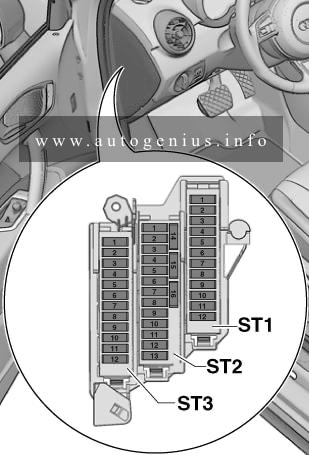
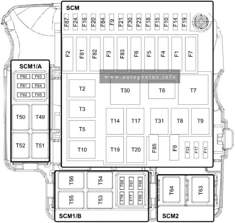
Passenger compartment
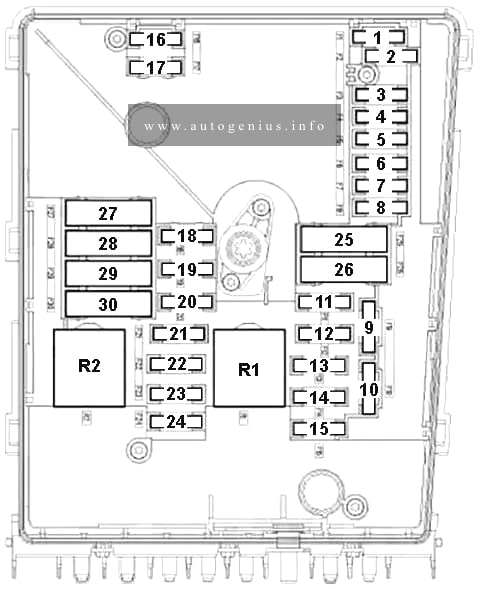
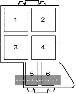
Fuses (SB) on fuse carrier B, left A-pillar (3)
Fuse box diagram
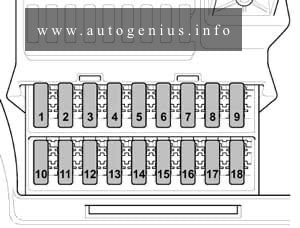
Assignment of the fuses and in the passenger compartment (holder SB)
| № | A | Function/component |
| 1 | 25 | Driver door control unit -J386- |
| 2 | 10 | Diagnostic connection -U31- |
| 3 | 25 | ABS control unit -J104- |
| 4 | 40 | ABS control unit -J104- |
| 5 | – | -Not used- |
| 6 | 7.5 | Evaluation unit for reducing agent level -G698- (from November 2008 to May 2009) Reverse flow valve for reducing agent -N473- (from November 2008 to May 2009) Pump for reducing agents -V437- (from November 2008 to May 2009) -Not used- (from May 2009) Supply unit for reducing agent metering system -GX19- (from November 2013) NOx sensor control unit -J583- (from November 2013) Relay 1 for voltage supply -J701- (from November 2013) NOx sensor 2 control unit -J881- (from November 2013) Relay for reducing agent metering system -J963- (from November 2013) Pump for reducing agent -V437- (from November 2013) |
| 7 | 30 | Headlight washer system pump -V11- |
| 8 | 15 | Rotating light and siren system switch -E11- (from July 2006) Switch for rotating light -E162- (from July 2006) Alarm horn -H12- Alarm system relay 1 -J460- Siren system relay 2 -J645- (From July 2006) |
| 9 | 10 | Turn signal relay for roof mounted turn signals -J436- (from May 2007) |
| 10 | 15 | Radio -R- Control unit with display for radio and navigation -J503- |
| 11 | 7.5 | Mobile telephone operating electronics control unit -J412- Tachograph control unit -J621- |
| 12 | 30 | Heater/heat output switch -E16- Fresh air blower relay -J13- Fresh air blower control unit -J126- Fresh air blower -V2- |
| 13 | 7.5 | Pre-selection clock -E111- Remote control receiver for auxiliary coolant heater -R149- |
| 14 | 30 | Operating unit for centre dash panel -J819- |
| 15 | 10 | Load area illumination switch -E481- (to October 2008) Not used |
| 16 | 10 | Heater/heat output switch -E16- A/C control module -J301- CD changer -R41- |
| 17 | 10 | Interior illumination switch -E599- Rear interior lamp switch -E6- (from November 2012 to May 2013) |
| 18 | – | Not used |
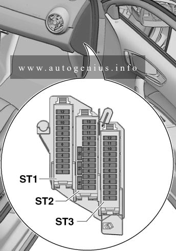
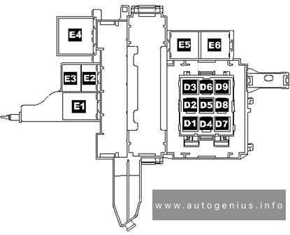
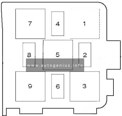
Fuses (SC) in fuse holder C, on left A-pillar (4)
Fuse box diagram
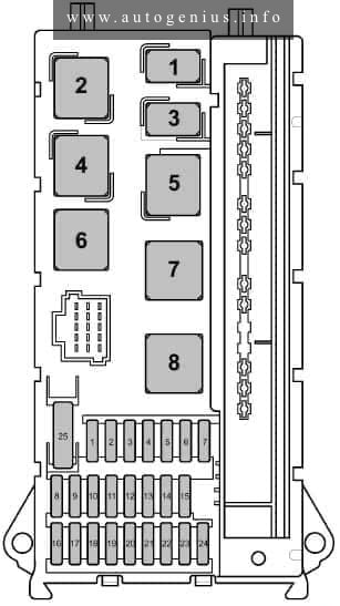
Assignment of the fuses and in the passenger compartment (holder SC)
| № | A | Function/component |
| 1 | 15 | Treble horn -H2- |
| 2 | 25 | Electronic ignition lock -D9- El. steer. col. lock CU -J764- |
| 3 | 10 | Electronic ignition lock -D9- Control unit in dash panel insert -J285- Engine control unit -J623- (from May 2012) |
| 4 | 5 | Light switch -E1- Operating unit for centre dash panel -J819- |
| 5 | 30 | Windscreen wiper motor -V- |
| 6 | 15 | Fuel system pressurisation pump -G6- |
| 7 | 5 | Steering column electronics control unit -J527- |
| 8 | 20 | Engine control unit -J623- |
| 9 | 20 25 |
Fuse 6 on fuse holder B -SB6- (from November 2008 to May 2009) Fuse holder D -SD- SD34 – SD36 (from May 2009 to November 2013) |
| 10 | 10 | Air mass meter -G70- (from May 2012) Evaluation unit for reducing agent level -G698- (from May 2012) Heater element for crankcase breather -N79- (from May 2012) Fuel pressure regulating valve -N276- Exhaust gas recirculation cooler changeover valve -N345- (from May 2012) Reverse flow valve for reducing agent -N473- (from May 2012) Exhaust gas recirculation cooler pump -V400- (from May 2012) Pump for reducing agent -V437- (from May 2012) |
| 11 | 15 | Relief relay 2 for terminal 15 -J817- (only for models in the 3.8 t weight class) Fuse 1 on fuse holder D -SD1- Fuse 2 on fuse holder D -SD2- |
| 12 | 10 | Airbag control unit -J234- |
| 13 | 15 | Glove compartment light switch -E26- Cigarette lighter -U1- |
| 14 | 5 | Light switch -E1- Control unit in dash panel insert -J285- Diagnostic connection -U31- |
| 15 | 5 | Heater/heat output switch -E16- Headlight range control regulator -E102- Left headlight range control motor -V48- Right headlight range control motor -V49- |
| 16 | 10 | Main switch for stop/start system -E101- Gearbox neutral position switch -F365- Oil level and oil temperature sender -G266- Fuel pump relay -J17- Continued coolant circulation relay -J151- Automatic glow period control unit -J179- Terminal 50 voltage supply relay -J682- Starter relay 1 -J906- (after November 2013) Starter relay 2 -J907- (after November 2013) Charge pressure control solenoid valve -N75- Coolant circuit valve -N214- Exhaust flap valve -N220- (after November 2013) Fuel metering valve -N290- Exhaust gas recirculation cooler changeover valve -N345- Lambda probe heater -Z19- |
| 17 | 10 | Airbag control unit -J234- |
| 18 | 7.5 | Brake light switch -F- (from July 2006 to November 2011) Brake pedal switch -F63- (from July 2006 to November 2011) Relief relay for terminal 15 -J404- Voltage stabiliser -J532- (after November 2011) Relay for special constructions, terminal 15 -J821- (after November 2011) Relief relay 3 for terminal 15 -J896- (from November 2011) |
| 19 | 7.5 | Onboard supply control unit -J519- (Interior light) |
| 20 | 25 | Onboard supply control unit -J519- |
| 21 | 5 | Air mass meter -G70- Engine control unit -J623- |
| 22 | 5 | Brake light switch -F- (before June 2006) Brake pedal switch -F63- (before June 2006) Lateral acceleration sensor -G200- (from July 2006) Longitudinal acceleration sensor -G251- (from July 2006) ABS control unit -J104- (From July 2006) |
| 23 | 25 | Starter -B- Onboard supply control unit -J519- |
| 24 | 10 | -Reserve Kl. 15- Battery regulation control unit -J840- (from May 2013) |
| 25 | 30 | -12-V socket -U5- |
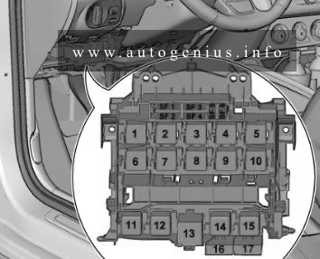
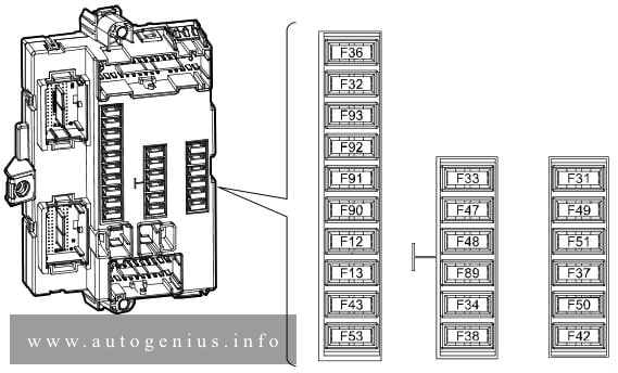
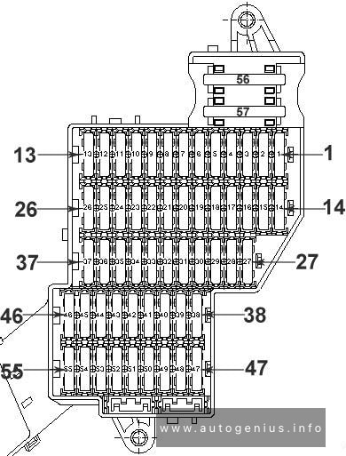
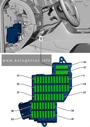
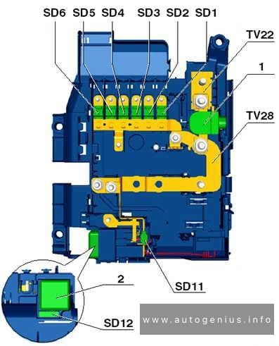
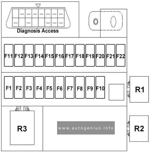
Fuses (SD) on fuse holder D, under driver seat, until May 2011 (5)
Fuse box diagram
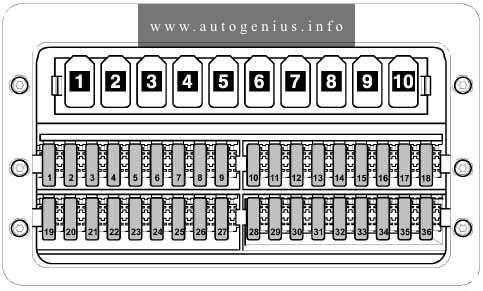
Assignment of the fuses and in the passenger compartment (holder SD – until May 2011)
| № | A | Function/component |
| 1 | 5 | Operating unit for window regulator in driver door -E512- Heated rear window relay -J9- (before June 2006) Relay 2 for heated rear window -J868- (From July 2006) |
| 2 | 30 | Rear left wing door window wiper motor -V92- Rear window wiper motor in right wing door -V93- |
| 3 | 5 | Pre-selection clock -E111- Gearbox neutral position switch -F365- Display unit control unit -J146- Mobile telephone operating electronics control unit -J412- (until May 2011) Reversing camera -R189- |
| 4 | 7.5 | Working speed control switch -E261- (from July 2006) Power take-off warning switch -F247- (from July 2006) Relay for heated rear window -J9- (until June 2006) Trailer detector control unit -J345- Tachograph control unit -J621- (From July 2006) |
| 5 | 5 / 10 | Selector lever -E313- Automated manual gearbox control unit -J514- |
| 6 | 5 | Battery regulation control unit -J840- (until May 2013) Heater element for crankcase breather -N79- |
| 7 | 10 | Fuel filter heater -Z57- |
| 8 | 5 / 10 | Tilting mechanism button -E223- Relay for special constructions, terminal 15 -J821- 6-pin connector -T6ah- (from May 2007) 7-pin connector -T7f- (Tail lift coupling point) |
| 9 | 15 | Switch for roof ventilator to ventilate loading area -E534- Siren system relay -J408- |
| 10 | 25 | -Interface for external use- |
| 11 | 15 | Relay for special constructions, terminal 15 -J821- |
| 12 | 10 | Relay for special constructions, terminal 61 -J822- |
| 13 | 30 / 10 | Evaporator blower control unit -J349- (from May 2007 to May 2011) Turn signal relay for roof mounted turn signals -J436- (To May 2007) |
| 14 | 20 | Trailer detector control unit -J345- (Before August 2006) 9-pin connector -T9b- (Preliminary set-up for trailer attachment from September 2006) Trailer socket -U10- (From September 2006) |
| 15 | 25 | Trailer detector control unit -J345- |
| 16 | 7.5 | Parking aid control unit -J446- Tyre Pressure Monitoring System control unit -J502- |
| 17 | 25 | Control unit for programmable special functions -J820- |
| 18 | 25 | Control unit for programmable special functions -J820- |
| 19 | 5 / 25 | Roof electronics control unit -J528- |
| 20 | 7.5 / 10 | Continued coolant circulation relay -J151- Entry and footwell light relay -J348- (from May 2009) |
| 21 | 15 / 30 | Heated rear window relay -J9- |
| 22 | 15 | Heated rear window relay -J9- (before June 2006) Relay 2 for heated rear window -J868- |
| 23 | 10 / 15 | Load area illumination switch -E481- (after November 2008) 12 V socket 2 -U18- |
| 24 | 15 | 12 V socket 4 -U20- |
| 25 | 15 | 12 V socket 3 -U19- |
| 26 | 25 | Auxiliary heater control module -J364- |
| 27 | 20 / 25 | Auxiliary heater control module -J364- Control unit 2 for supplementary heating -J824- |
| 28 | 30 / 40 | Evaporator blower control unit -J349- (before April 2007) Gearbox hydraulic pump relay -J510- (from May 2007) |
| 29 | 15 | Automated manual gearbox control unit -J514- |
| 30 | 40 | Gearbox hydraulic pump relay -J510- (before April 2007) Battery regulation control unit -J840- |
| 31 | 30 / 15 | Rear fresh air blower control unit -J391- Left sliding door control unit -J558- Rear fresh air blower -V80- |
| 32 | 5 | Battery monitoring control unit -J367- |
| 33 | 15 | Right sliding door control unit -J731- |
| 34 | 15 | Control unit for reducing-agent heater -J891- (from April 2009) |
| 35 | 15 / 3 | Control unit for reducing-agent heater -J891- (from April 2009) |
| 36 | – | Not used |
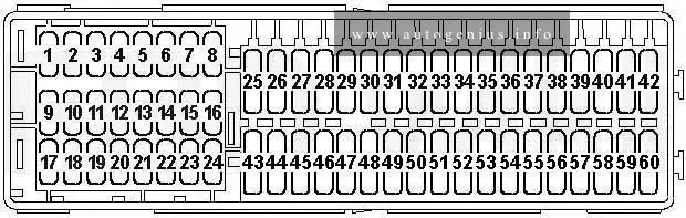
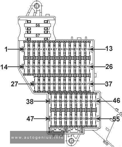
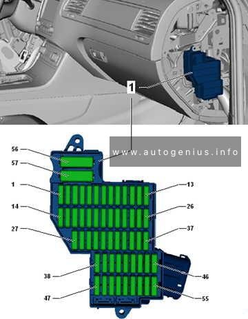
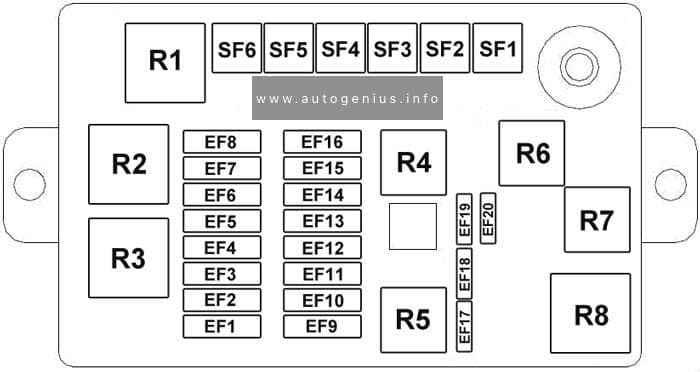
Fuses (SD) on fuse holder D, under driver seat, after May 2011 (5)
Fuse box diagram
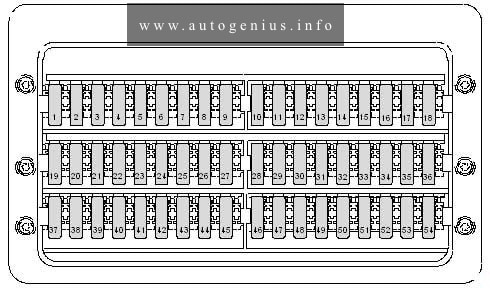
Assignment of the fuses and in the passenger compartment (holder SD – after May 2011)
| № | A | Function/component |
| 1 | 5 | Operating unit for window regulator in driver door -E512- Heated rear window relay 2 -J868- |
| 2 | 30 | Rear left wing door window wiper motor -V92- Rear window wiper motor in right wing door -V93- |
| 3 | 5 | Pre-selection clock -E111- Gearbox neutral position switch -F365- Display unit -J145- Reversing camera -R189- |
| 4 | 7.5 | Working speed control switch -E261- Power take-off warning switch -F247- Trailer detector control unit -J345- Tachograph control unit -J621- |
| 5 | 5 / 10 | Selector lever -E313- Automated manual gearbox control unit -J514- Bonnet contact switch -F266- (from November 2011) |
| 6 | 5 / 10 | Heater element for crankcase breather -N79- Battery regulation control unit -J840- (from May 2011 to May 2013) |
| 7 | 10 | Fuel filter heater -Z57- |
| 8 | 5 / 10 | Tilting mechanism button -E223- Parking aid control unit -J446- (after May 2013) Relay for special constructions, terminal 15 -J821- (until November 2011) 6-pin connector -T6ah- 7-pin connector -T7f- (Tail lift coupling point) |
| 9 | 15 | Switch for roof ventilator to ventilate loading area -E534- (before November 2011) Siren system relay -J408- (before November 2011) -nicht belegt (ab November 2011)- |
| 10 | 25 | -Schnittstelle für externe Nutzung- |
| 11 | 15 | Relay for special constructions, terminal 15 -J821- |
| 12 | 10 | Relay for special constructions, terminal 61 -J822- |
| 13 | – | Not used |
| 14 | 20 | 9-pin connector -T9b- (Preliminary set-up for trailer attachment) Trailer socket -U10- |
| 15 | 25 | Trailer detector control unit -J345- |
| 16 | 7.5 | Parking aid control unit -J446- Tyre Pressure Monitoring System control unit -J502- |
| 17 | 25 | Control unit for programmable special functions -J820- |
| 18 | 25 | Control unit for programmable special functions -J820- |
| 19 | 5 / 25 | Roof electronics control unit -J528- |
| 20 | 7.5 / 10 | Continued coolant circulation relay -J151- Entry and footwell light relay -J348- |
| 21 | 30 | Heated rear window relay -J9- |
| 22 | 15 | Heated rear window relay 2 -J868- |
| 23 | 10 / 15 | Load area illumination switch -E481- 12 V socket 2 -U18- |
| 24 | 15 | 12 V socket 4 -U20- |
| 25 | 15 | 12 V socket 3 -U19- |
| 26 | 25 | Auxiliary heater control module -J364- |
| 27 | 20 / 25 | Auxiliary heater control module -J364- Control unit 2 for supplementary heating -J824- |
| 28 | 40 / 30 | Gearbox hydraulic pump relay -J510- Starter relay 1 -J906- |
| 29 | 15 | Automated manual gearbox control unit -J514- |
| 30 | 5 | Battery regulation control unit -J840- |
| 31 | 30 / 15 | Left sliding door control unit -J558- (from May 2012) Rear fresh air blower control unit -J391- Rear fresh air blower -V80- |
| 32 | 5 | Battery monitoring control unit -J367- |
| 33 | 15/30/7,5 | Not used Right sliding door control unit -J731- (from May 2012) Lockout relay 1 for transfer box -J1010- (from January 2012) Lockout relay 2 for transfer box -J1011- (from January 2012) Lockout relay 3 for transfer box -J1012- (from January 2012) Compressed air compressor -V534 – (From January 2012) |
| 34 | 15 / 7.5 | Control unit for reducing-agent heater -J891- Transfer box differential lock switch -F99- (from January 2012) Rear axle drive unit differential lock switch -F100- (from January 2012) Front axle drive unit differential lock switch -F101- (From January 2012) |
| 35 | 15 / 3 | Control unit for reducing-agent heater -J891- Compressed air compressor protection control unit -J1013- (From January 2012) |
| 36 | 5 | Not used (to January 2012) Compressed air compressor pressure switch -F503- (From January 2012) |
| 37 | – | Not used |
| 38 | – | Not used |
| 39 | 7.5 / 15 | Switch for roof ventilator to ventilate loading area -E534- (after November 2011) Siren system relay -J408- (from November 2011) |
| 40 | – | Not used |
| 41 | – | Not used |
| 42 | 30 | Evaporator blower control unit -J349- |
| 43 | – | Not used |
| 44 | – | Not used |
| 45 | – | Not used |
| 46 | – | Not used |
| 47 | – | Not used |
| 48 | – | Not used |
| 49 | – | Not used |
| 50 | – | Not used |
| 51 | – | Not used |
| 52 | – | Not used |
| 53 | – | Not used |
| 54 | – | Not used |
| 55 | – | Not used |
| 56 | – | Not used |
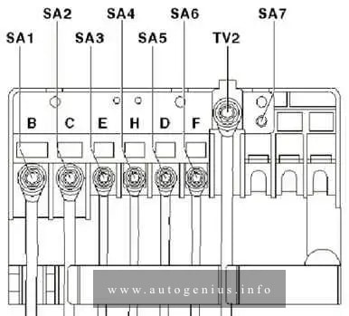
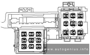
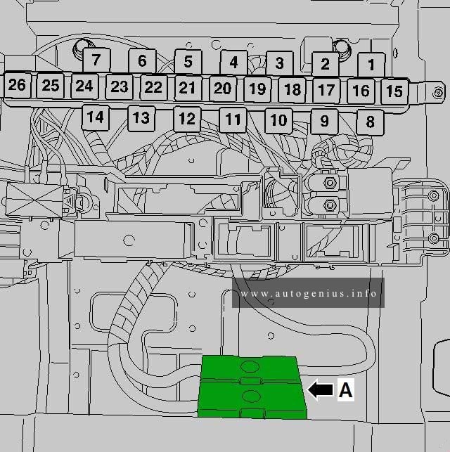
Single fuses under driver seat (fuses for special vehicles until May 2013)
Fuse box diagram
A – Tipping mechanism fuse -S186- Up to August 2006
A – Fuse 1 (30) -S204- (Retarder/Second battery)
A – Fuse 2 (30) -S205- after September 2006 (Tail lift/three-way tipper/Retarder)
A – Main fuse for multiple equipment configurations -S245- Up to August 2006
Single fuses under driver seat (fuses for special vehicles after May 2013 )
Fuse box diagram
A – Fuse 1 (30) -S204- (Retarder/Second battery)
A – Fuse 2 (30) -S205- (Tail lift/three-way tipper/Retarder)
Fuse 1 -S131-
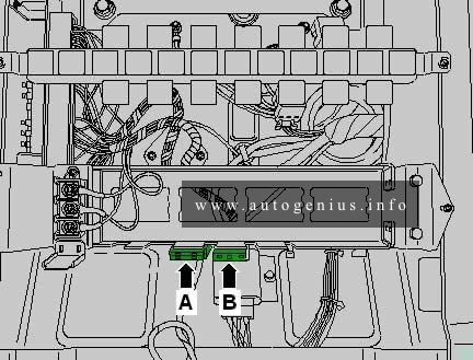
A – Daytime running lights fuse -S220- (Achleitner only)
B – Fuse 1 -S131- (Compressed air compressor)
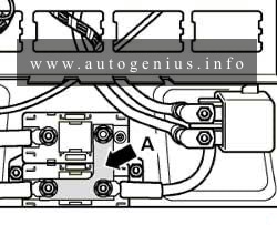
Terminal 30 voltage supply fuse -S190- (1)
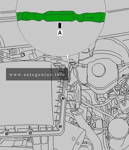
A – Terminal 30 voltage supply fuse -S190- (in the line section between the alternator and the starter)
WARNING: Terminal and harness assignments for individual connectors will vary depending on vehicle equipment level, model, and market.