Chevrolet Equinox (2006) – fuse and relay box diagram
Year of production: 2006
This article focuses on the first-generation Chevrolet Equinox, manufactured between 2005 and 2009. It includes fuse box diagrams for the 2006 models, details the locations of the fuse panels within the vehicle, and provides information on the function and layout of each fuse and relay.
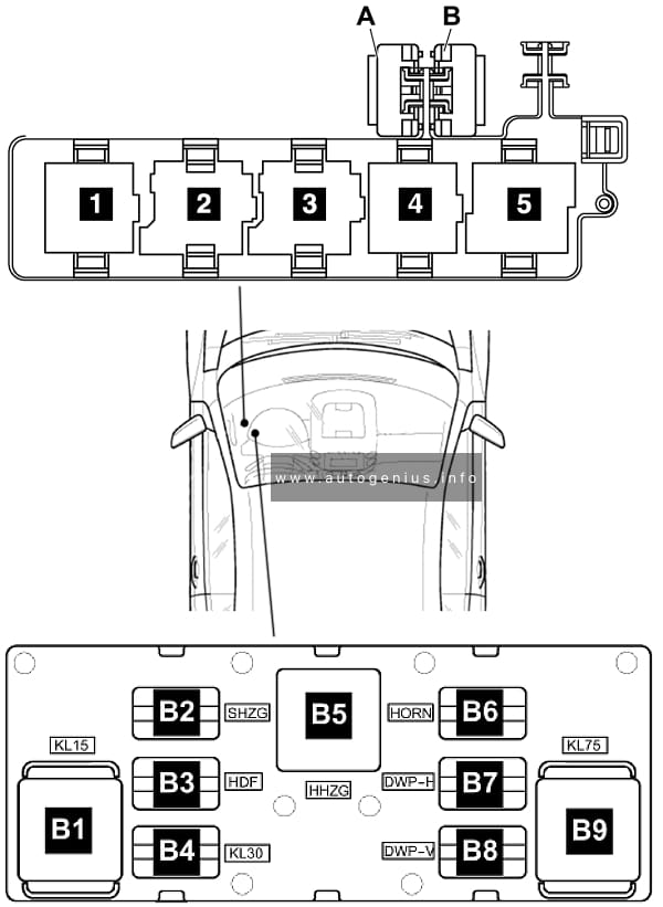
Passenger compartment
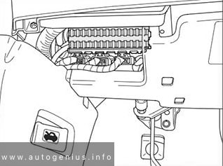
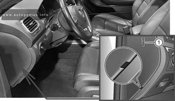
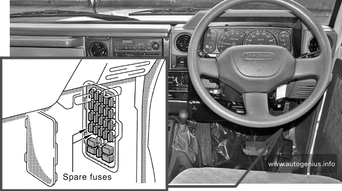
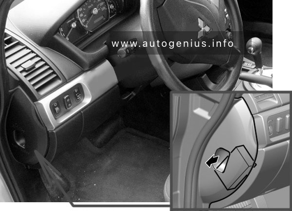
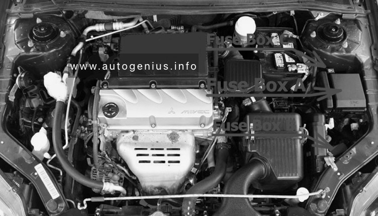
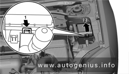
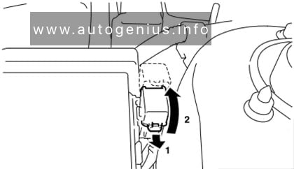
Fuse Box Location
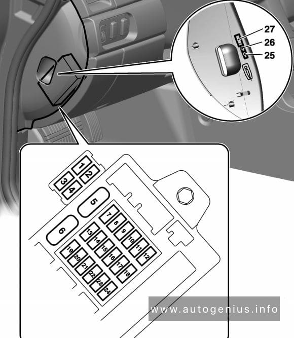
The fuse box is located under the dashboard on the passenger’s side of the center console, behind the cover.
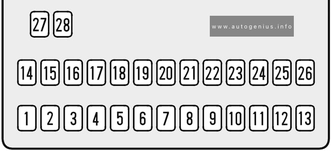
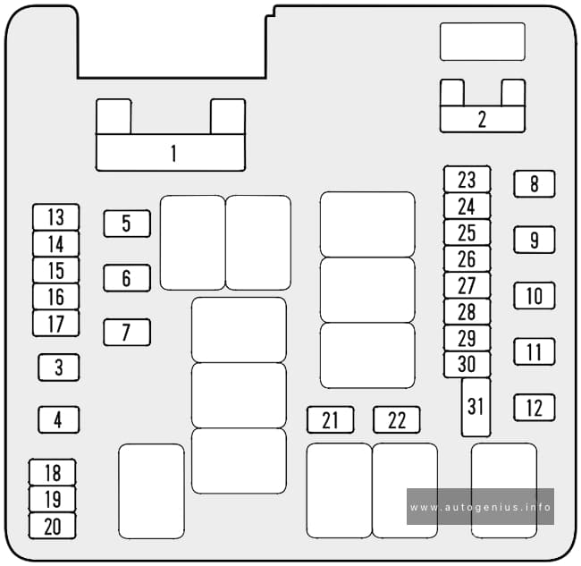
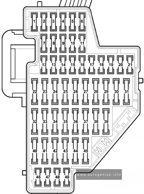
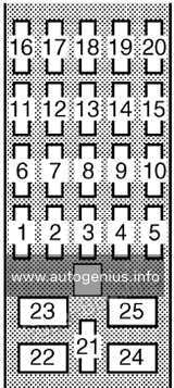
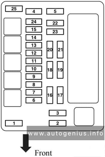
Fuse Box Diagram
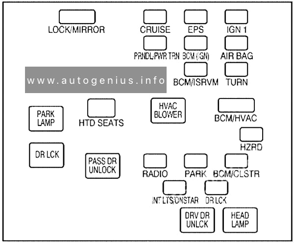
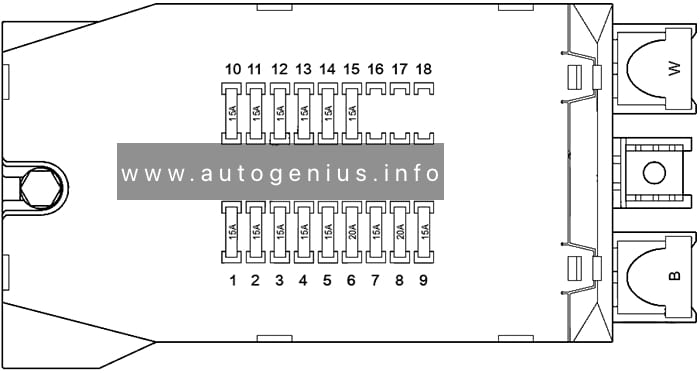
Assignment of the fuses and relays in the passenger compartment
| Name | Description |
|---|---|
| LOCK/MIRROR | Door Lock, Power Mirror |
| CRUISE | Cruise Control System |
| EPS | Electric Power Steering |
| IGN 1 | Switches, Instrument Panel Cluster |
| PRNDL/ PWR TRN | PRNDL/Powertrain |
| BCM (IGN) | Body Control Module |
| AIRBAG | Airbag System |
| BCM/ISRVM | Body Control Module, Inside Rearview Mirror |
| TURN | Turn Signals |
| HTD SEATS | Heated Seats |
| BCM/HVAC | Body Control Module, Heating, Ventilation and Air Conditioning |
| HZRD | Hazard Warning Flashers |
| RADIO | Radio |
| PARK | Parking Lamps |
| BCM/CLSTR | Body Control Module, Instrument Panel Cluster |
| INT LTS/ ONSTAR | Interior Lights/OnStar |
| DR LCK | Door Locks |
| Relays | |
| PARK LAMP | Parking Lamps Relay |
| HVAC BLOWER | Heating, Ventilation and Air Conditioning Blower Motor |
| DR LCK | Door Locks Relay |
| PASS DR UNLOCK | Passenger Door Unlock Relay |
| DRV DR UNLCK | Driver Door Unlock Relay |
| HEAD LAMP | Headlamps |
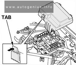
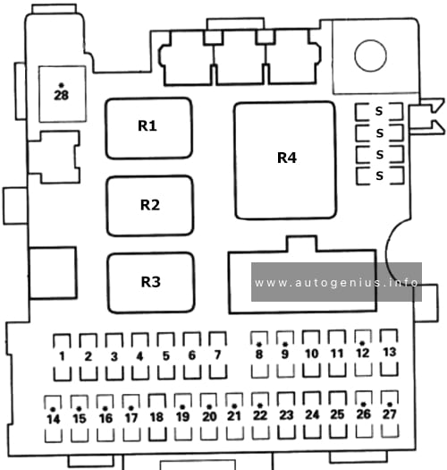
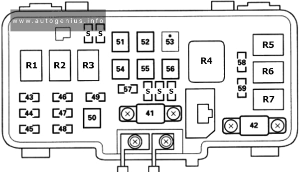
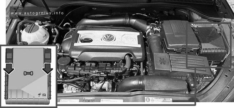
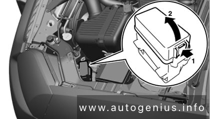
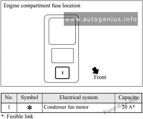
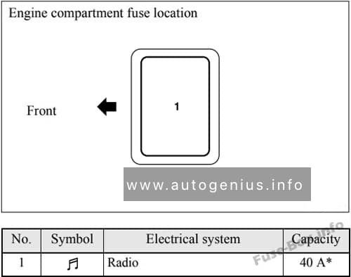
Engine Compartment
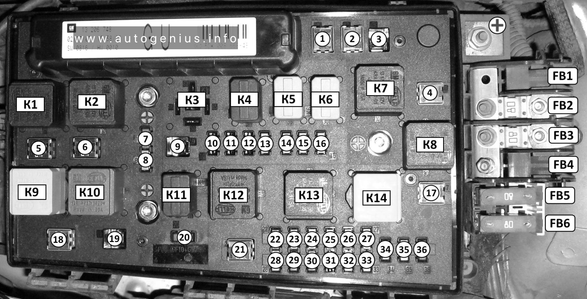
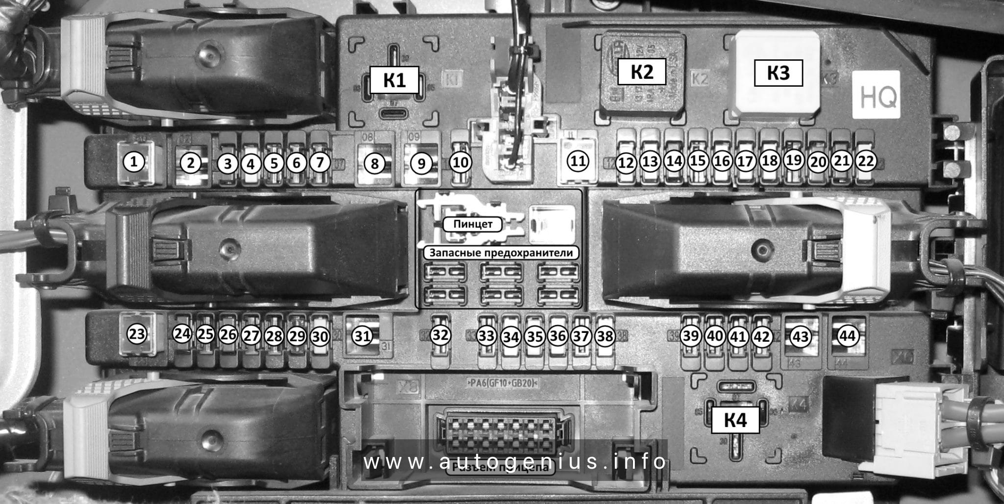
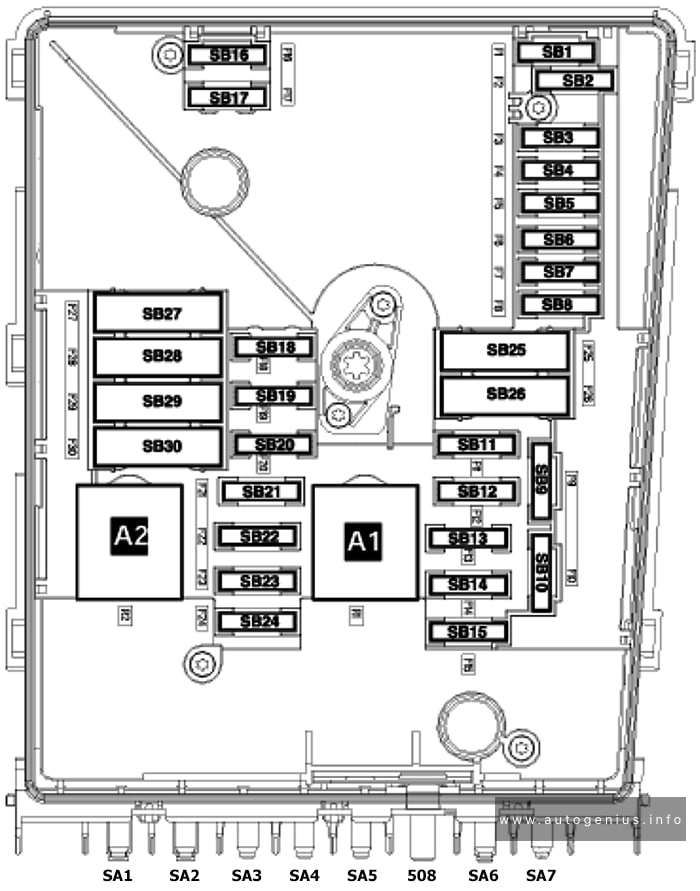
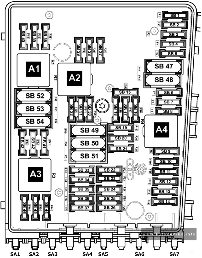
Fuse Box Diagram
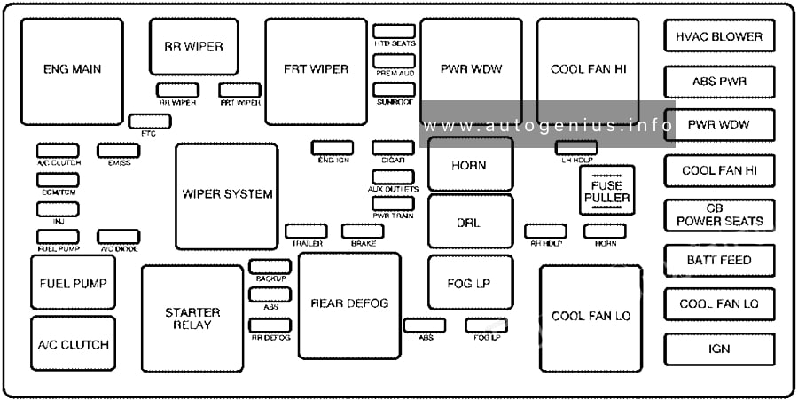
Assignment of the fuses and relays in the engine compartment
| Name | Description |
|---|---|
| HTD SEATS | Heated Seats |
| HVAC BLOWER | Heating, Ventilation, Air Conditioning Blower Control |
| PREM AUD | Premium Audio System, Amplifier |
| ABS PWR | Anti-lock Brake System |
| RR WIPER | Rear Window Wiper |
| FRT WIPER | Front Window Wiper |
| SUNROOF | Sunroof |
| ETC | Electronic Throttle Control |
| PWR WDW | Power Windows |
| A/C CLUTCH | Air Conditioning Clutch |
| EMISS | Emissions |
| ENG IGN | Engine Ignition |
| CIGAR | Cigarette Lighter |
| LH HDLP | Left Headlamp |
| COOL FAN HI | Cooling Fan High |
| ECM/TCM | Engine Control Module, Transaxle Control Module |
| AUX OUTLETS / AUX1 OUTLET |
Accessory Power Outlets |
| FUSE PULLER | Fuse Puller |
| INJ | Fuel Injectors |
| PWR TRAIN | Powertrain |
| FUEL PUMP | Fuel Pump |
| A/C DIODE | Air Conditioning Diode |
| TRAILER | Trailer Lighting |
| AUX 2/CARGO | Accessory Power Outlet 2, Cargo Outlet |
| BRAKE | Brake System |
| RH HDLP | Right Headlamp |
| HORN | Horn |
| BACKUP | Back-up Lamps |
| BATT FEED | Battery |
| ABS | Anti-lock Brake System |
| COOL FAN LO | Cooling Fan Low |
| RR DEFOG | Rear Window Defogger |
| START | Ignition |
| ABS | Anti-lock Brake System |
| FOG LP | Fog Lamps |
| IGN | Ignition Switch |
| CB POWER SEATS | Power Seats (Circuit Breaker) |
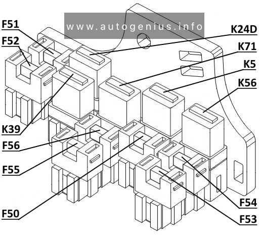
| Relays | |
| ENG MAIN | Engine Relay |
| RR WIPER | Rear Window Wiper Relay |
| FRT WIPER | Front Window Wiper Relay |
| PWR WDW | Power Windows Relay |
| COOL FAN HI | Cooling Fan High Relay |
| WIPER SYSTEM | Wiper System Relay |
| HORN | Horn Relay |
| DRL | Daytime Running Lamps Relay |
| FUEL PUMP | Fuel Pump Relay |
| STARTER RELAY | Starter Relay |
| REAR DEFOG | Rear Window Defogger Relay |
| FOG LP | Fog Lamp Relay |
| COOL FAN LO | Cooling Fan Low Relay |
| A/C CLUTCH | Air Conditioning Clutch Relay |
WARNING: Terminal and harness assignments for individual connectors will vary depending on vehicle equipment level, model, and market.