Chevrolet Lumina (1996) – fuse and relay box diagram
Year of production: 1996
This article focuses on the second-generation Chevrolet Lumina, manufactured from 1994 to 2001. It provides fuse box diagrams for the 1996 models, along with details on the location of the fuse panels within the vehicle and explanations of each fuse and relay assignment (fuse layout).
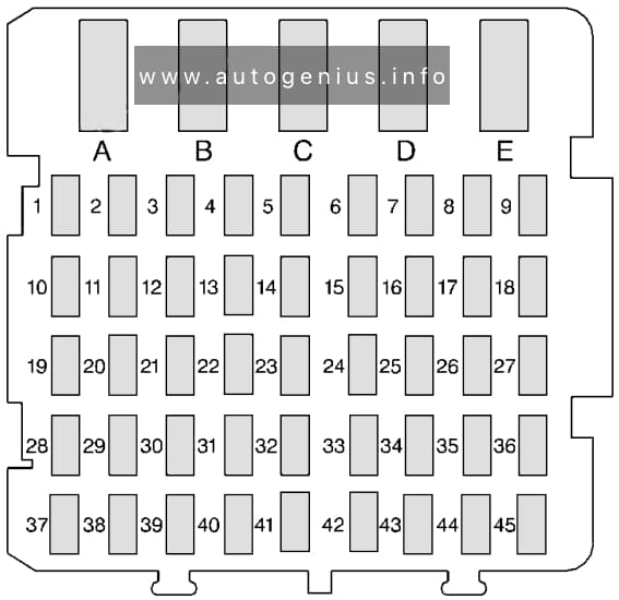
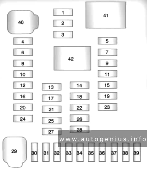
Instrument Panel Fuse Block
Fuse box diagram

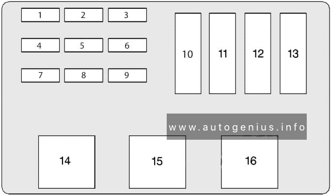
Assignment of the fuses in the instrument panel (1996)
| Fuse | Description |
| 1 | CIGAR LIGHTER — Instrument Panel and Console Cigar Lighter |
| 2 | — |
| 3 | DRL MDL |
| 4 | HVAC #2 — HVAC Control Assembly, Soloneid Box |
| 5 | HAZARD FLASHER |
| 6 | POWER ACCESSORY #2 — Sunroof Control Unit |
| 7 | — |
| 8 | — |
| 9 | — |
| 10 | I/P ELECTRONICS BATTERY FEED — Chime Module, Electronic Brake Control Module (EBCM), Theft Deterrent Module, Radio |
| 11 | STARTER RELAY |
| 12 | ANTI-THEFT — Theft Deterrent Module |
| 13 | ABS — Electronic Brake Control Module (EBCM), ABS Relay |
| 14 | HVAC BLOWER MOTOR — Blower Motor Relay |
| 15 | HVAC #1 — Air Temperature Valve Motor, Daytime Running Lamps Module (with DRL), HVAC Control Assembly, Multifunction Lever Cruise Control Switch |
| 16 | REAR DEFOG — HVAC Control Assembly Rear Window Defogger Switch |
| 17 | — |
| 18 | — |
| 19 | POWER ACCESSORY #1– Trunk Courtesy Lamp, Door Lock Switches, Power Mirror Switch |
| 20 | POWER ACCESSORY (Power) #1 – Door Lock Switches, Trunk Courtesy Lamp, O/S Mirror Switch |
| 21 | AIR BAG — Air Bag System |
| 22 | — |
| 23 | STOPLAMPS — TCC/Brake Switch |
| 24 | CRUISE CONTROL |
| 25 | — |
| 26 | — |
| 27 | — |
| 28 | CTSY LAMPS — Vanity Mirrors, Defogger Relay, I/P Compartment Lamp, Header Courtesy and Reading Lamp, I/S Lighted Rearview Mirror, Dome Lamp |
| 29 | WIPER — Wiper Switch |
| 30 | TURN SIGNAL — Turn Signal Flasher |
| 31 | — |
| 32 | POWER LOCKS — Door Lock Relay, Keyless Entry Receiver |
| 33 | — |
| 34 | — |
| 35 | — |
| 36 | — |
| 37 | — |
| 38 | RADIO — Radio, Steering Wheel Radio Switches |
| 39 | I/P ELECTRONICS IGNITION FEED — Headlamp Switch, Cruise Control Cut-Out Switch, Sensing and Diagnostic Module (SDM), TCC/Brake Switch, Instrument Cluster, Chime Module, Keyless Entry Receiver |
| 40 | — |
| 41 | — |
| 42 | — |
| 43 | — |
| 44 | — |
| 45 | — |
| Circuit Breaker | |
| A | — |
| B | — |
| C | Power Windows |
| D | Power Seats |
| E | — |
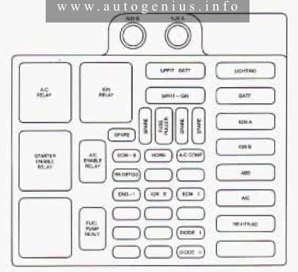
Engine Compartmet Fuse Box (Passenger Side)
Fuse box diagram
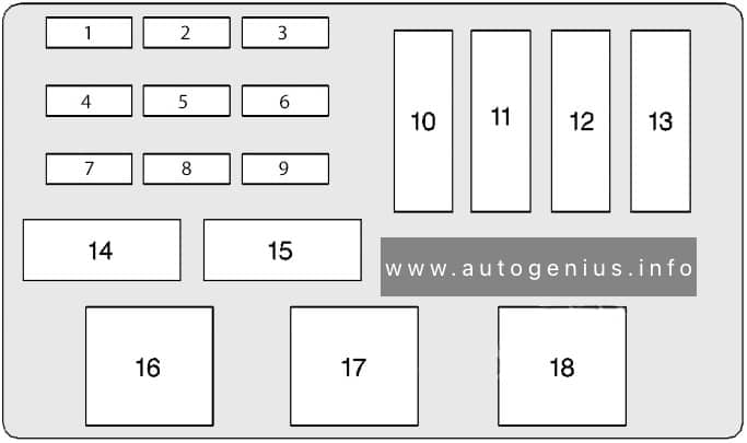
Assignment of the fuses in the engine compartment fuse box №1 – Passenger Side (1996)
| No | Fuse | Description |
| 1 | A.I.R. PMP | A.I.R. Relay |
| 2 | R/CMPT REL | Remote Trunk Release |
| 3 | ECM BAT | Powertrain Control Module (PCM), Fuel Pump/Oil Pressure Switch, Fuel Pump Relay, Fan Cont #1 Relay |
| 4 | TCC | Automatic Transaxle, Transaxle Range Switch (VIN M onl |
| 5 | ENG EMIS | A/C CMPR Relay (VIN M only) |
| 6 | Automatic Transaxle, Transaxle Range Switch (VIN M only) | |
| 7 | F/INJN | Fuel Injectors |
| 8 | ECM IGN | Powertrain Control Module (PCM), Mass Air Flow (MAF) Sensor (VIN X only), EGR, CCP, Oxygen Sensor, Vacuum Canister Switch, Fan #2 Relay |
| 9 | ELEK IGN | Electronic Ignition (EI) Control Module |
| 10 | I/P Fuse Block | |
| 11 | FAN CONT #1 Relay | |
| 12 | Passenger Side Underhood Electrical Center and I/P Fuse Blocks: Fuses 5, 14,23 and 32 | |
| 13 | FAN CONT #2 Relay and I/P Fuse Block: Fuse 16, Power Seat Circuit Breaker “D” | |
| Relay | ||
| 14 | FUEL PUMP | FUEL PUMP |
| 15 | A/C CMPR | A/C CMPR |
| 16 | FAN CONT #2 | Secondary Cooling Fan (Passenger Side) |
| 17 | FAN CONT #1 | Primary Cooling Fan (Driver Side) |
| 18 | Ignition Relay | |
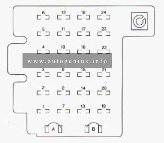
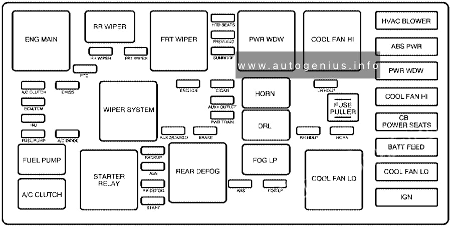
Engine Compartmet Fuse Box (Driver Side)
Fuse box diagram
Assignment of the fuses in the engine compartment fuse box №2 – Driver Side (1996)
| No | Fuse | Usage |
| 1 | — | — |
| 2 | — | — |
| 3 | — | — |
| 4 | FOG LPS | Fog Lamps |
| 5 | PARK LPS | Headlamp Switch |
| 6 | HORN | Horn Relay, Underhood Lam |
| 7 | ABS | Anti-Lock Brake System |
| 8 | — | — |
| 9 | VAR P/S | EVO Steering |
| 10 | IGN SW2 | I/P Rise Block: PWR WDO and Circuit Breaker D; Passenger’s Side Underhood Electrical Center: TCC and ENG EMIS Fuses; |
| 11 | IGN SW1 | I/P Fuse Block: Radio, Wiper, HVAC, ABS and Turn Signal Fuses; Passenger’s Side Underhood Electrical Center: F/IJN, ECM IGN and ELEK IGN Fuses; |
| 12 | HD LPS | Circuit Breaker to Headlamp Switch |
| 13 | ABS | ABS Relay |
| Relay | ||
| 14 | ABS | Anti-Lock Brake System |
| 15 | — | — |
| 16 | HORN | Horn |
WARNING: Terminal and harness assignments for individual connectors will vary depending on vehicle equipment level, model, and market.