Ferrari 458 (2009 – 2015) – fuse box diagram

Ferrari 458 (2009 – 2015) – fuse box diagram

Year of production: 2009, 2010, 2011, 2012, 2013, 2014, 2015

Location

458 Spider

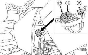
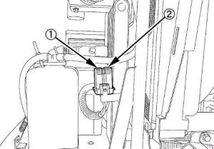
Ferrari 458 - fuse box diagram - location
Ferrari 458 – fuse box diagram – location

458 Speciale

Ferrari 458 - fuse box diagram - location
Ferrari 458 – fuse box diagram – location
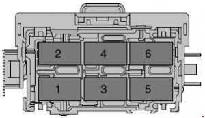
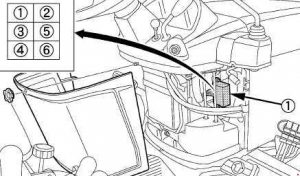
Number Description
A Fuses and relays in battery compartment
B Body computer fuses and relays
C Fuses and relays in passenger compartment on passenger side
D Fuses and relays on driver-side rear side panel

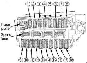
Body Computer fuses and relays

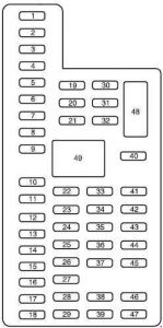
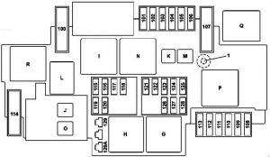
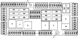
Ferrari 458 - fuse box diagram - body computer
Ferrari 458 – fuse box diagram – body computer
Number Fuse rating [A] Description
F12 15 Right high beam
F13 15 Left high beam
F31 7,5 ENT/A for dashboard ECU and Body Computer Node relay coils
F32 10 Dome lights, foot well and step lights. Side Marker relay coil
F33 30 Speciale: Left hand Brembo EPB system motor
F34 30 Spider:Suspension Control Node
Speciale:
Right hand Brembo EPB system motor
F35 7,5 Stop light control, clutch control, air conditioning node
F36 10 Volumetric and-theft system, parking sensors, fuel filler flap relay coil
F37 10 Stop light control, Instrument Panel Node, Suspension Control Node
F38 15 Luggage compartment lock actuator
F39 15 Dashboard ECU devices (NBC interconnection)
F40 30 Heated rear window
F42 7,5 Alternator
15 Speciale: USB charging socket
F43 30 Windscreen washer/wiper relay power supply
F44 20 Passenger seat heating, cigarette lighter
F47 30 Driver-side door, driver-side power window
F48 30 Passenger-side door, passenger-side power window
F49 7,5 Rain and twilight sensor, parking sensors, parking brake control, column adjustment control, hazard warning lights, Steering Wheel Node, Differential Control Node, radio, CAN box interface
F50 7,5 Airbag Node, weight sensor
F51 7,5 Semi-automatic Gearbox Node
F52 15 Power socket, driver seat heating
F53 10 Instrument Panel Node power supply
Relay
T01 20 Low beam relay
T11 30 Heated rear screen relay
T12 30 Service relay 1 (dependent on INT/A ignition switch)
T13 50 Jumper (service power supply 2)

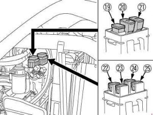
Fuses and relays in passenger compartment on passenger side

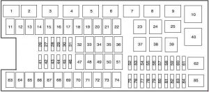
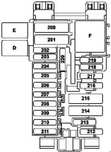
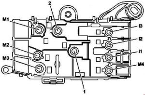
Ferrari 458 - fuse box diagram - passenger compartment (passenger side)
Ferrari 458 – fuse box diagram – passenger compartment (passenger side)
Number Ampere ratting [A] Description
F01 60 Spider: +30 Radiator fan relay 2
40 Speciale: Right hand radiator fan relay
F02 30 Spider: +30 ABS (valves)
Speciale: F97, F98 protection fuses for ABS
F03 30 Spider: +30 Hard top Node (pump)
F04 50 +30 ABS (pump)
F05 40 +30 Air conditioning Node
F06 50 Spider: +30 Radiator fan relay 1
40 Speciale: Left hand radiator fan relay
F07 20 +30 Horn relay
F08 7,5 Air conditioning and heating system compressor
F09 7,5 +30 Supplementary stop light relay (third stop light)
F10 15 Spider: +30 Fuel pump relay 1
Speciale: Tyre pressure monitoring system + DRL ECU
F11 25 Left bank oxygen sensor
F14 15 Spider: +30 High beam relay
10 Speciale: +30 High beam relay
F15 7,5 Spider: +30 Power supply for EPB-activated stop light control relay, right headlight LED module power supply relay
10 Speciale: +30 Power supply for EPB-activated stop light control relay, right headlight LED module power supply relay
F16 25 +30 Right bank engine control power supply
F17 25 +30 Left bank engine control power supply
F18 10 +30 Left cylinder bank injection system power supply, LH cylinder bank injection main relay
F19 10 +30 Right cylinder bank injection system power supply
F20 30 +30 Right cylinder bank injection system main relay
F21 15 Spider: +30 Fuel pump relay 2
30 Speciale: +30 Ignition switch protection
F22 15 Left bank (ignition coil)
F23 10 Spider: +30 ABS (electronic)
30 Speciale: Suspension Control Node
F24 15 Right bank (ignition coil)
F30 30 +30 HI-FI amplifier relay
F81 40 Spider: +30 Supplementary ECU power siupply
50 Speciale: Fuel pump ECU
F82 70 +30 Dashboard ECU and ECU oi rear side panel power supplyii driver-side
F83 50 +30 Air pump relay
F84 15 Spider: +30 Fuel pump relay 1
30 Speciale: Protection for fuses F94 F95 F96
F85 25 Headlight washer
F87 25 Right bank oxygen sensors
F88 10 +15 Left cylinder bank injection system
F89 10 +15 Right cylinder bank injection system
F91 15 Spider: +30 Tyre pressure node, LH headlight LED module relay
10 Speciale: Left hand cylinder bank sensors
F92 7,5 Spider: +30 Alternator sensing
10 Speciale: Right hand cylinder bank sensors
F93 30 Spider: +30 Ignition switch
7,5 Speciale: Ionising engine ECU
F94 15 +30 Radio/CAN box/ICP/dock spring/Japan navigation system stabiliser
F95 10 +30 Current stabiliser
F96 7,5 Speciale: +15 ignition switch, stabilised for buttons
F97 30 Spider: +30 Stabiliser for Becker amplifier
Speciale: ABS hydraulics
F98 10 Speciale: ABS electronics
Relay
T02 30 High beam relay
T03 30 Spider: Fuel pump second speed relay
T05 30 Spider: Fuel pump relay 2
T06 30 Spider: Glove compartment relay
T07 50 Horn relay
T08 30 Air conditioning and heating system compressor relay
T09 30 Left cylinder bank injection system main relay
T10 30 Right cylinder bank injection system main relay
T14 30 Spider: Fuel pump relay 1
T17 10 INT/A relay (devices excluded at ignition)
20
T19 30 EPB-activated stop light control relay
T20 30 Spider: Starting relay
T26 10 Windscreen wiper first speed relay
20
T27 10 Windscreen wiper second speed relay
20
T28 30 Windscreen washer pump relay
T29 30 Supplementary stop light relay (third stop light)
T30 50 Air pump relay
T31 30 Headlight washer pump relay
T37 30 Spider: Radiator fan relay 2
Speciale: +15 stabilised power for button backlighting
T38 30 Left headlight LED module power supply
T39 30 Right headlight LED module power supply
T40 30 Spider: Radiator fan relay 1
Speciale: Start enable relay

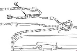
Fuses and relays on driver-side rear side panel

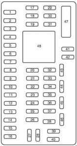
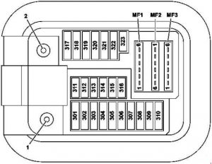
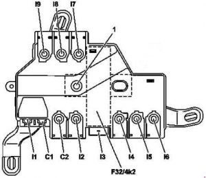
Ferrari 458 - fuse box diagram - driver-side rear side panel
Ferrari 458 – fuse box diagram – driver-side rear side panel
Number Fuse rating [A] Description
F54 15 +30 Gearbox cooling fan
F56 30 Spider: +30 Driving Position Node
F57 7,5 Side Markers 1 (LH front and RH rear)
F59 7,5 Reverse light power supply
F60 30 Spider: +30 Passenger Position Node
Speciale: Active aerodynamics
F61 7,5 +30 Driver Position Node (electronic), front lift
F62 7,5 Spider: +30 Passenger Position Node (electronic)
F63 15 Spider: +30 Semi-automatic gearbox main relay
20 Speciale: +30 Semi-automatic gearbox main relay
F64 7,5 Fuel filler flap actuator power supply
F65 20 +30 Door lock actuator
F66 7,5 +30 Semi-automatic Gearbox Node
F67 7,5 Side Markers 2 (RH front and LH rear)
F78 15 +30 Battery charger
F80 30 +30 Starting relay
Relay
T21 50 Side Marker relay
T22 30 Reverse light relay
T23 30 Fuel filler flap relay
T24 30 Gearbox cooling fan relay
T25 30 Semi-automatic gearbox main relay
T43 30 Spider: Start enable relay
R1 Starter power relay
R2 Starter power relay

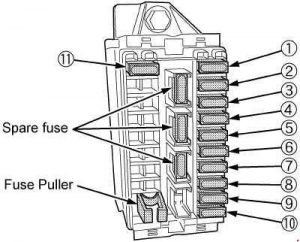
Fuses and relays in battery compartment

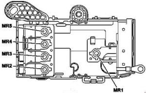
Ferrari 458 - fuse box diagram - battery compartment
Ferrari 458 – fuse box diagram – battery compartment
Number Fuse rating [A] Description
CAL5 CAL5 Power supply (starter motor and alternator)
F70 150 Engine relay and fuse ECU power supply (SCM)
F71 40 Front lift pump
F72 40 Spider: Parking brake power
F73 70 Dashboard ECU power

WARNING: Terminal and harness assignments for individual connectors will vary depending on vehicle equipment level, model, and market.

Ferrari California (2008 – 2014) – fuse box diagram

Ferrari California (2008 – 2014) – fuse box diagram

Year of production: 2008, 2009, 2010, 2011, 2012, 2013, 2014

Location

Ferrari California - fuse box diagram - location
Ferrari California – fuse box diagram – location
Number Description
A Fuses and relays in engine compartment
B Body computer fuses and relayu
C Fuses and relays in passenger compartment on passenger side
D Fuses and relays in passenger compartment in center console

Body Computer fuses and relays

Ferrar California - fuse box diagram - body computer
Ferrar California – fuse box diagram – body computer
Number Fuse rating [A] Description
F12 15 Right high beam
F13 15 Left high beam
F31 7,5 AC unit, body computer connector
F32 10 Dome lights, foot well and puddle lights, side markers, supplementary taillights.
F35 7,5 Clutch pedal control. Cruise control. Power steering. Beams.
F36 10 Satellite alarm system, parking sensors, fuel filler flap.
F37 10 Stop light control.
F38 15 Luggage compartment lock
F39 15 Radio, diagnosis socket, CAN box interface.
F40 30 Heated rear screen
F42 7,5 Alternator
F43 30 Windscreen wipers
F44 20 Passenger seat heating, cigarette lighter
F46 20 Hard top
F47 30 Driver-side door
F48 30 Passenger-side door
F49 7,5 Passenger compartment lighting switches and controls
F50 7,5 Air bags
F51 7,5 Semi-automatic gearbox, engine start button
F52 15 Power socket driver seat heating
F53 10 Instrument panel
Relay
T01 20 Low beam relay
T11 30 Heated rear screen relay
T12 30 Relay services 1
T13 Supply jumper services 2

Passenger side fuses and relays

Ferrari California - fuse box diagram - passenger side
Ferrari California – fuse box diagram – passenger side
Number Ampere ratting [A] Description
F01 60 +30 Radiator fans (first speed)
F02 30 +30 ABS (valves)
F03 30 +30 Ignition switch
F04 50 +30 ABS (pump)
F05 40 +30 Air conditioning and heating system
F06 50 +30 Radiator fans (second speed)
F07 20 +30 Horns
F08 7,5 Air conditioning and heating system compressor
F09 7,5 +30 Supplementary stop lights
F10 15 +30 luggage compartment lock relay
FII 25 Left bank oxygen sensors
F14 15 +30 high beams
F15 7,5 +30 alternator sensing
F16 25 +30 Right bank engine control power supply
F17 25 +30 Left bank engine control power supply
F18 10 +30 Left cylinder bank injection system power supply, LH cylinder bank injection main relay
F19 10 +30 Right cylinder bank injection system power supply, RH cylinder bank injection main relay coil
F20 30 +30 right injection system main relay
F21 15 +30 Fuel pump 2
F22 15 Left bank (ignition coil)
F23 10 +30 ABS (electronic)
F24 15 Right bank (ignition coil)
F30 30 +30 Starting relay
F81 40 +30 Supplementary ECU power supply
F82 70 +30 Dashboard ECU and luggage compartment ECU power supply
F83 50 +30 Air pump relay
F84 15 +30 Fuel pump relay 1
F85 25 Headlight washer
F87 25 Right bank oxygen sensors
F88 10 +15 left cylinder bank injection system
F93 30 +30 suspension control node fuse
Relay
T02 30 High beam relay
T05 30 Fuel pump relay 2
T06 30 Luggage compartment lock actuator relay
T07 50 Horn relay
T08 30 Air conditioning and heating system compressor relay
T09 30 Left cylinder bank injection system main relay
T10 30 Right cylinder bank injection system main relay
T14 30 Fuel pump relay 1
T15 50 Radiator fan relay (second speed)
T16 50 Radiator fan relay (first speed)
T17 10 INT/A relay (devices excluded at ignition)
20
T19 30 Stop light control relay
T20 30 Starting relay
T26 30 Windscreen wiper relay (first speed)
T27 30 Windscreen wiper relay (second speed)
T28 30 Windscreen washer pump relay
T29 30 Supplementary stop light relay (third stop light)
T30 50 Air pump relay
T37 30 Left supplementary taillight relay
T38 30 Left headlight LED module power supply
T39 30 Right headlight LED module power supply
T31 30 Headlight washer pump relay

Fuses and relays on centre console

Ferrari California - fuse box diagram - centre console
Ferrari California – fuse box diagram – centre console
Number Fuse rating [A] Description
F54 20 +30 HI-FI amplifier
F56 30 +30 Driving position
F57 7,5 Side Markers 1 (LH front and RH rear)
F59 7,5 Reverse lights
F60 30 +30 Passenger position
F61 7,5 +30 Driving position (electronic)
F62 7,5 +30 Passenger position (electronic)
F63 15 +30 Semi-automatic gearbox main relay
F64 7,5 Fuel filler flap actuator
F65 20 Door lock actuator
F66 7,5 +30 Semi-automatic gearbox
F67 7,5 Side Markers 2 (RH front and LH rear)
F78 15 +30 Battery charger
F80 30 +30 BassBox amplifier
Relay
T21 50 Side Marker relay
T22 30 Reverse light relay
T23 30 Fuel filler flap relay
T24 30 Supplementary taillight relay
T25 30 Semi-automatic gearbox main relay

Fuses and relays in the engine compartment

Ferrari California - fuse box diagram - engine compartment
Ferrari California – fuse box diagram – engine compartment
Number Fuse rating [A] Description
CAL2 CAL2 Power sitpply (starter motor and alternator).
F70 150 Power sitpply and engine relay
F71 40 Hard top pump
F72 40 Parking brake power
F73 70 Dashboard ECU power

WARNING: Terminal and harness assignments for individual connectors will vary depending on vehicle equipment level, model, and market.

Ferrari 328 (1986 – 1989) – fuse box diagram

Ferrari 328 (1986 – 1989) – fuse box diagram

Year of production: 1986, 1987, 1988, 1989

Fuse box

Ferrari 328 - fuse box diagram
Ferrari 328 – fuse box diagram
Number Fuse rating [A] Description
1 25 Electric motor for high/low beams – R.H. heater
2 25 L.H. heater
3 15 Daylight flashing – Current socket – Door locking – Interior lights
4 15 Hazard – Cigar lighter – Aerial – Parking lights
5 20 Electro-fan for A C. condenser
6 20 Left electro-fan for water radiator
7 20 Right electro-fan for water radiator
8 20 Horns – Clock – Radio
9 7,5 Cold start electro-valve
10 15 L.H. main beam and relevant warning light
11 15 R.H. main beam
12 10 L.H. dipped beam
13 10 R.H. dipped beam
14 7,5 Front lights – Rear lights
15 7,5 Front lights – Rear lights
16 15 Parking lights lamp – Instrument panel lights -Front fog lights
17 20 Air conditioning system
18 20 L.H. window motor
19 20 R.H. window motor
20 15 Fuel pump
21 7,5 Instrument – Displays for heater controls – Ext. rear view mirrors
22 15 Windscreen wiper – Windscreen washer – Reverse light
23 15 Direction indicator lights – Stop rear lights

Number Relay Part No.
A Relay for heater blowers 0 332 014 113
B Relay for R.H. head-lamp lifting motor 0 332 204 101
C Relay for high/low wiper speed 0 332 204 101
D Relay for head-lamps lifting motor 0 332 204 101
E Relay for L.H. head-lamps, lifting motor 0 332 204 101
F Relay for electro-fan of A C. condenser 0 332 014 113
G Relay for left electro-fan of water radiator 0 332 014 113
H Warning horn relay 0 332 014 113
K Relays for heater blowers 0 332 014 113
J Flasher for direction indicators
1 Relay for right electro-fan of water 0 332 014 113
L Relay for low beams 0 332 014 113
M Relay for high beam headlamps 0 332 014 113
N Relay for flashing 0 332 014 113
O Relay for external lights 0 332 015 006
P Relay for Air Conditioning operation 0 332 204 101
Q Relay for windows motors 0 332 014 113
R Relay for fuel pump 0 332 014 113
S Fuel injection delivery pump starting-relay 0 332 204 101
T Relay for light lifting motors (with low beams on) 0 332 014 113
U Relay for key controlled services 0 332 014 113
V Relay for air conditioner control 0 332 014 113
X Windshield wiper timing relay
Y Timer for interior lights.
Z Relay for A.C. compressor 0 332 014 113
W Seat belts control unit

WARNING: Terminal and harness assignments for individual connectors will vary depending on vehicle equipment level, model, and market.

Ferrari F430 (2004 – 2009) – fuse box diagram

Ferrari F430 (2004 – 2009) – fuse box diagram

Year of production: 2004, 2005, 2006, 2007, 2008, 2009

Location

Ferrari F430 - fuse box diagram - location
Ferrari F430 – fuse box diagram – location
Number Location
A Power fuses
B Luggage compartment fuses
C Fuses in the passenger compartment, RH side (behind RH seat)
D Fuses in the passenger compartment, LH side (behind LH seat)
E Megafuse (behind the battery)

Luggage compartment fuses and relays

Ferrari F430 - fuse box diagram - luggage compartment
Ferrari F430 – fuse box diagram – luggage compartment
Number Fuse rating [A] Description
AF1 15 High beams
AF2 25 Low beams
AF3 7,5 RH high beam
AF4 15 RH low beam
AF5 7,5 Number plate lights, switch lights
AF6 15 Taillights
AF7 7,5 LH high beam
AF8 15 LH low beam
AF9 5 +30 Instrument panel, Bluetooth control unit
AF10 15 Horns
AF11 Position available
AF12 Position available
AF13 30 Headlight washers
AF14 30 Front lid actuator
AF15 5 + 15 Instrument panel, internal light timing ECU, child safety, passenger airbag deactivation
AF16 5 RH front and LH rear position lights
AF17 15 Blinking internal lights, hazard blinking indicators and direction indicators
AF18 15 Dashboard glove compartment
AF19 Position available
AF20 5 LH front and RH rear position lights
Relay
AR1 30 LH Fan
AR2 30 RH Fan
AR3 30 Lid opening actuator
AR4 30 Child safety
AR5 20 High beams
AR6 20 Low beams
AR7 20 Dashboard glove compartment
AR8 Position available
AR9 20 Position lights
AR10 20 Parking lights
AR11 20 Number plate lights, switch lights
AR12 20 Horns

Right-hand side passenger compartment fuses and relays

Ferrari F430 - fuse box diagram - passenger compartment (right hand-side)
Ferrari F430 – fuse box diagram – passenger compartment (right hand-side)
Number Fuse rating [A] Description
PDF1 10 +15 RH Motronic, Pin 86 on PDR8 and PDR9 relays
PDF2 7,5 Rear fog lights
PDF3 7,5 External rear view mirror defroster
PDF4 15 RH Lambda sensors
PDF5 15 Stop lights
PDF6 25 +30 Windscreen wiper
PDF7 30 Heated rear window
PDF8 10 Positive from main RH relay. (PDR10)
PDF9 20 +15 Radio, rear view mirror switch, fuel tank flap, direction indicators switch, cigarette lighter, parking sensors
PDF10 30 +30 Radio, radio amplifier, parking sensors
PDF11 Position available
PDF12 15 Air fl ow meter, exhaust bypass valve, antievaporation diagnostic pump, anti-evaporation valve, immobilizer relay, intake manifold valve, A.C. relay
PDF13 5 +15 Alarm system, immobilizer
PDF14 5 +30 Alarm system, immobilizer
PDF15 Position available
PDF16 15 RH ignition coils, RH injectors
PDF17 15 Windscreen washer/ wiper
PDF18 15 +30 key
PDF19 Position available
PDF20 10 RH Timing variators
PDF21 7,5 +30 RH Motronic
PDF22 Position available
PDF23 30 RH Motronic (main)
PDF24 10 +15 ABS – ASR – ESP
PDF25 15 +30 Fuel pump relay 1 (PDR8) and fuel pump relay 2 (PDR9)
PDF26 10 +87 Tyre pressure monitoring system (TPMS)
Relay
PDR1 Immobilizer (spec. BOSCH switch)
PDR2 30 Key-operated devices
PDR3 30 Heated rear window/ rear view mirror defroster
PDR4 20 Rear fop lights
PDR5 30 +30 Windscreen wiper
PDR6 20 +15 Windscreen wiper
PDR7 20 +Heated seats
PDR8 20 RH fuel pump – Speed 1 (BOSCH)
PDR9 20 RH fuel pump. – Speed 2 (BOSCH)
PDR10 20 Main for RH Motronic CBOSCH)

Left-hand side passenger compartment fuses and relays

Ferrari F430 - fuse box diagram - passenger compartment (left hand-side)
Ferrari F430 – fuse box diagram – passenger compartment (left hand-side)
Number Fuse rating [A] Protected component
PSF1 10 + 15 LH Motronic, +86 on LH fuel pump relays. (PSR8 and PSR9)
PSF2 20 FI ECU
PSF3 30 +30 RH power window
PSF4 15 LH Lambda sensor
PSF5 7,5 + 15 shock absorber damping (Skyhook), +15 alternator, +1S electric differential
PSF6 IS +30 Door locking system
PSF7 30 +30. LH power window
PSF8 10 Positive from main LH Motronic relay. (PSR10)
PSF9 10 +1S Airbag
PSF10 15 Battery charger
PSF11 10 +30 Engine control system (OBD), +30 tyre pressure monitoring system (TPMS), +30 electronic differential
PSF12 15 Air flow meter, exhaust bypass valves, anti-evaporation diagnostic pump, anti-evaporation valve
PSF13 10 +15 Air Conditioning system, + 15 recirculation pump
PSF14 30 Starter motor
PSF15 15 Ceiling light, door lights, glove compartment lights, parking light control
PSF16 15 LH ignition coil LH injectors
PSF17 Position available
PSF18 Position available
PSF19 15 A.C. compressor
PSF20 10 LH timing variator
PSF21 7,5 +30 LH Motronic
PSF22 10 Reverse light
PSF23 30 LH Motronic. (main)
PSF24 15 Power socket
PSF25 15 +30 fuel pump relay 1 (PSR8) and fuel pump relay 2 (PSR9)
PSF26 5 +15 connected devices relay (excluding ignition)
PSF27 20 +Heated seats
PSF28 60 +30 rear LH module guard
PSF29 60 +30 rear RH module guard
PSF30 Position available
PSF31 30 FI Pump/E-DTFF
PSF32 Position available
Relay
PSR1 20 A.C. Compressor
PSR2 20 Reverse gear switch
PSR3 20 Key-operated devices
PSR4 20 Cutout switch for disabling starting with battery charger (normally closed)
PSR5 20 Connected devices switch (excluding ignition)
PSR6 30 Starter motor
PSR7 20 Ignition anti-repeat
PSR8 20 LH fuel pump – Speed 1 (BOSCH)
PSR9 20 LH fuel pump. – Speed 2 (BOSCH)
PSR10 20 Main for LH Motronic (BOSCH)
PSR12 50 FI Pump

Power fuses

Ferrari F430 - fuse box diagram - power fuses
Ferrari F430 – fuse box diagram – power fuses
Number Ampere ratting [A] Description
MAXI 1 50 +30 RH Fan
MAXI 2 50 +30 LH Fan
MAXI 3 50 +30 A.C.
MAXI 4 60 +30 front guard
MAXI 5 20 +30 alternator sensing
MAXI 6 60 +30 ABS/ASR/ESP
MAXI 7 30 RH seat
MAXI 8 30 LH seat

Megafuse

Ferrari F430 - fuse box diagram - megafuses
Ferrari F430 – fuse box diagram – megafuses
Ferrari F430 - fuse box diagram - megafuses
Ferrari F430 – fuse box diagram – megafuses

WARNING: Terminal and harness assignments for individual connectors will vary depending on vehicle equipment level, model, and market.

Ferrari FF (2011 – 2016) – fuse box diagram

Ferrari FF (2011 – 2016) – fuse box diagram

Year of production: 2011, 2012, 2013, 2014, 2015, 2016

Location

Ferrari FF - fuse box diagram - location
Ferrari FF – fuse box diagram – location
Number Location
A Fuses and realys in the battery compartment
B Body computer fuses and relays
C Fuses and relays in the passenger compartment on passenger side
D Fuses and relays on centre console
E Fuses and relays in luggage compartment

Body Computer fuses and relays

B

Ferrari FF - fuse box diagram - body computer - box B
Ferrari FF – fuse box diagram – body computer – box B
Number Fuse rating [A] Description
F12 15 Right high beam
F13 15 Left high beam
F31 7,5 INT/A for dashboard ECU, Body Computer Node and air conditioning and heating relay
F32 10 Dome lights, foot well and step lights, Side Marker relay coil and glove compartment button
F33 30 Electronically controlled Gearbox Node control unit
F35 7,5 High beam relay coils, headlight washer, illumination of buttons, adaptive headlight ECU, headlights, power steering, entertainment system
F36 10 Parking sensors, fuel filler flap relay coil
F37 10 Instrument Panel Node
F38 15 Luggage compartment lock actuator, wiper control ECU
F39 15 EOBD socket, anti-theft system siren. Air Conditioning Node
F40 30 Heated rear window
F41 15 Windscreen washer nozzle demisting power supply
F42 7,5 Alternator
F43 30 T28. T29, T26, T27 relay power supply
F44 20 Passenger seat heating, cigarette lighter
F47 30 Driver-side door, driver-side power window
F48 30 Passenger-side door, passenger-side power window
F49 7,5 Rain sensor, parking sensors, seats, suspension lift, Japan navigation system, electrochromic mirror
F50 7,5 Airbag Node
F51 7,5 Electronically controlled Gearbox Node, ignition button
F52 15 Power socket, driver’s seat heating, wiper control ECU relay
Relay
T01 20 Low beam relay
T11 30 Heated rear window relay
T12 30 Service relay 1 (dependent on INT/A ignition switch)
T13 50 Jumper (service power supply 2)

Fuses and relays in passenger compartment on passenger side

C

Ferrari FF - fuse box diagram - passenger compartment - box C
Ferrari FF – fuse box diagram – passenger compartment – box C
Number Fuse rating [A] Description
F01 40 +30 Radiator fan relay 2
F02 40 +30 ABS (valves)
F03 70 Bus bar power supply for F-107, F-108, F-91, F-92, F-109, F-104, F-103
F04 50 +30 ABS (pump)
F05 40 +30 Air conditioning Node
F06 40 +30 electric radiator fan 1
F07 20 +30 Horn relay
F08 7,5 Air conditioning and heating system compressor
F09 7,5 +30 Alternator sensing
F10 30 +30 Bus bar for F-94, F-95, F-106
F11 25 Left bank oxygen sensor
F14 15 +30 High beam relay
F15 30 +30 Ignition switch
F16 25 +30 Right bank engine control power supply
F17 25 +30 Left bank engine control power supply
F20 30 +30 Right cylinder bank injection system power supply
F21 30 +30 4WD system hydraulic pump relay
F22 15 Left bank (ignition coil)
F24 15 Right bank (ignition coil)
F30 30 +30 Starting relay
F81 40 +30 Fuel pump ESD ECU
F82 70 +30 Dashboard ECU and luggage compartment ECU power supply
F83 50 +30 Air pump relay
F84 30 +30 Suspension Control Node
F85 25 Headlight washer
F87 25 Right bank oxygen sensors
F88 10 +15 Left cylinder bank injection system
F89 10 +15 Right cylinder bank injection system
F91 15 +30 Tyre pressure node, LH headlight LED module relay
F92 10 +30 RH headlight LED module relay, EPB-activated stop light control relay
F94 15 +30 Radio/CAN box/ICP/clock spring/Japan navigation system stabiliser
F95 10 +30 Current stabiliser
F102 10 +30 ABS (electronic)
F103 20 +30 4WD front differential ECU
F104 15 +30 4WD electric cooling fan relay
F105 30 +30 ABS (valves)
F106 7,5 +30 Passenger compartment control lighting
F107 10 +30 Right cylinder bank injection system power supply
F108 10 +30 Left cylinder bank injection system power supply, starting relay
F109 7,5 +30 Supplementary stop light relay
Relay
T02 30 High beam relay
T03 30 Passenger compartment control lighting relay
T05 30 Supplementary stop light relay
T06 30 Battery cooling fan relay (preset)
T07 50 Horn relay
T08 30 Air conditioning and headng system compressor relay
T09 30 Left cylinder bank injection system main relay
T10 30 Right cylinder bank injection system main
T14 30 4WD system electric cooling fan relay
T17 10 INT/A relay (devices excluded at ignition)
20
T19 30 EPB-activated stop light control relay
T20 30 Starting relay
T26 30 Windscreen wiper first speed relay
T27 30 Windscreen wiper second speed relay
T28 30 Windscreen washer pump relay
T29 30 Rear window washer pump relay
T30 50 Air pump relay
T31 30 Headlight washer pump relay
T38 30 Left headlight LED module power supply
T39 30 Right headlight LED module power supply
T40 30 Radiator fan relay 1

Fuses and relays on centre console

D

Ferrari FF - fuse box diagram - centre console - box D
Ferrari FF – fuse box diagram – centre console – box D
Number Fuse rating [A] Protected component
F54 30 +30 HiFi amplifier
F56 30 +30 Driving Position Node
F57 7,5 Side Markers 1 (LH front and RH rear)
F59 7,5 Reverse light power supply
F60 30 +30 Passenger Position Node
F63 20 +30 Electronically controlled gearbox main relay
F64 7,5 Fuel filler flap actuator power supply
F65 20 +30 Door lock actuator
F66 30 +30 Bus bar in CS-SCM3
F67 7,5 Side Markers 2 (RH front and LH rear)
F78 15 +30 Wiper control ECU relay
F80 30 +30 Bus bar power supply for F-97, F-98, F-99
Relay
T21 50 Side Marker relay
T22 30 Reverse light relay
T23 30 Fuel filler flap relay
T25 30 Electronically controlled gearbox main relay

Fuses and relays in luggage compartment

Ferrari FF - fuse box diagram - luggage compartment - box E
Ferrari FF – fuse box diagram – luggage compartment – box E
Number Ampere ratting [A] Description
F96 10 +30 Luggage compartment lock relay
F97 10 +30 Electronic Passenger Position Node, luggage compartment striker plate
F98 15 +30 Battery conditioner socket
F100 7,5 30 Driving Position Node, suspension lift ECU
F101 10 +30 Entertainment components
Relay
T40 30 Glove compartment lock relay
T41 30 Luggage compartment lid lock relay
T42 30 Wiper control ECU relay
T43 30 Cigarette lighter relay

Fuses and relays in battery compartment

A

Ferrari FF – fuse box diagram – battery compartment – box A
Number Ampere ratting [A] Description
CAL5 CAL5 Power supply (starter motor and alternator)
F70 150 Engine relay and fuse ECU power supply (SCM)
F71 40 Front lift pump
F72 40 Parking brake power
F73 70 Dashboard ECU power

WARNING: Terminal and harness assignments for individual connectors will vary depending on vehicle equipment level, model, and market.

Ferrari F12Berlinetta – fuse box diagram

Ferrari F12Berlinetta – fuse box diagram

Year of production:

Location

Ferrari F12Berlinetta - fuse box diagram - location
Ferrari F12Berlinetta – fuse box diagram – location
Number Location
A Fuses and realys in the battery compartment
B Body computer fuses and relays
C Fuses and relays in the passenger compartment on passenger side
D Fuses and relays on centre console
E Fuses and relays in luggage compartment

Body Computer fuses and relays

B

Ferrari F12Berlinetta - fuse box diagram - body computer - box A
Ferrari F12Berlinetta – fuse box diagram – body computer – box A
Number Fuse rating [A] Description
F12 15 Right high beam
F13 15 Left high beam
F31 7,5 INT/A for dashboard ECU, Body Computer Node and air conditioning and heating relay
F32 10 Dome lights, foot well and step lights, Side Marker relay coil and glove compartment button
F33 30 Electronically controlled Gearbox Node control unit
F35 7,5 Stop light control, clutch control, air conditioning node
F36 10 Parking sensors, fuel filler flap relay coil
F37 10 Instrument Panel Node
F38 15 Luggage compartment lock actuator
F39 15 Dashboard ECU devices (NBC interconnection)
F40 30 Heated rear window
F41 15 Heated nozzle power supply
F42 7,5 Alternator
F43 30 Windscreen washer/wiper relay power supply
F44 20 Passenger seat heating, cigarette lighter
F47 30 Driver-side door, driver-side power window
F48 30 Passenger-side door, passenger-side power
F49 7,5 Rain and twilight sensor, parking sensors, parking brake control, column adjustment control, hazard warning lights. Steering Wheel Node, Differential Control Node, radio, CAN box interface
F50 7,5 Airbag Node, weight sensor
F51 7,5 Electronically controlled Gearbox Node, ignition button
F52 15 Power socket, driver seat heating
Relay
T01 20 Low beam relay
T11 30 Heated rear window relay
T12 30 Service relay 1 (dependent on INT/A ignition switch)
T13 50 Jumper (service power supply 2)

Fuses and relays in passenger compartment on passenger side

C

Ferrari F12Berlinetta - fuse box diagram - passenger compartment - box C
Ferrari F12Berlinetta – fuse box diagram – passenger compartment – box C
Number Fuse rating [A] Description
F01 40 +30 Radiator fan relay 2
F02 40 Bus-Bar power supply for F-102, F-105
F03 70 Bus bar power supply for F-107, F-108, F-91, F-92, F-109, F-104, F-103
F04 50 +30 ABS (pump)
F05 40 +30 Air conditioning Node
F06 40 +30 Radiator fan relay 1
F07 20 +30 Horn relay
F08 7,5 Air conditioning and heating system compressor
F09 7,5 +30 Alternator sensing
F10 30 +30 Bus bar for F-94, F-95, F-106
F11 25 Left bank oxygen sensor
F14 15 +30 High beam relay
F15 30 +30 Ignition switch
F16 25 +30 Right bank engine control power supply
F17 25 +30 Left bank engine control power supply
F19 20 +30 Active aerodynamic relay
F20 30 +30 Right cylinder bank injection system main
F21 10 +30 Active aerodynamic control and front lift power supply
F22 15 Left bank (ignition coil)
F24 15 Right bank (ignition coil)
F30 30 +30 Starting relay
F81 40 +30 Fuel pump ESD ECU
F82 70 +30 Dashboard ECU and luggage compartment ECU power supply
F83 50 +30 Air pump relay
F84 30 +30 Suspension Control Node
F85 25 Headlight washer
F87 25 Right bank oxygen sensors
F88 10 +15 Left cylinder bank injection system
F89 10 +15 Right cylinder bank injection system
F91 15 +30 Tyre pressure node, LH headlight LED module relay
F92 7,5 +30 Right headlight LED module relay
F94 15 +30 Radio/CAN box/ICP/clock spring/Japan navigation system stabiliser
F95 10 +30 Current stabiliser
F102 10 +30 ABS (electronic)
F105 30 +30 ABS (valves)
F106 7,5 +30 Passenger compartment control lighting
F107 10 +30 Right cylinder bank injection system power supply
F108 10 +30 Left cylinder bank injection power supply
F109 7,5 +30 Supplementary stop light relay
Relay
T02 30 High beam relay
T03 30 Passenger compartment control lighting relay
T05 30 Supplementary stop light relay
T07 50 Horn relay
T08 30 Air conditioning and headng system compressor relay
T09 30 Left cylinder bank injection system main relay
T10 30 Right cylinder bank injection system main
T14 30 Windscreen washer pump relay
T17 10 INT/A relay (devices excluded at ignition)
20
T19 30 EPB-activated stop light control relay
T20 30 Starting relay
T26 30 Windscreen wiper first speed relay
T27 30 Windscreen wiper second speed relay
T28 30 Active aerodynamic release relay
T29 30 Active aerodynamic locking relay
T30 50 Air pump relay
T31 30 Headlight washer pump relay
T38 30 Left headlight LED module power supply
T39 30 Right headlight LED module power supply

Fuses and relays on centre console

D

Ferrari F12Berlinetta - fuse box diagram - centre console - box D
Ferrari F12Berlinetta – fuse box diagram – centre console – box D
Number Fuse rating [A] Protected component
F54 30 +30 HiFi amplifier
F56 30 +30 Driving Position Node
F57 7,5 Side Markers 1 (LH front and RH rear)
F59 7,5 Reverse light power supply
F60 30 +30 Passenger Position Node
F63 20 +30 Electronically controlled gearbox main relay
F64 7,5 Fuel filler flap actuator power supply
F65 20 +30 Door lock actuator
F66 30 +30 Bus-Bar power supply for F-96, F-100, F-I01
F67 7,5 Side Markers 2 (RH front and LH rear)
F80 30 +30 Bus bar power supply for F-97, F-98, F-99
Relay
T21 50 Side Marker relay
T22 30 Reverse light relay
T23 30 Fuel filler flap relay
T25 30 Electronically controlled gearbox main relay

Fuses and relays in luggage compartment

Ferrari F12Berlinetta - fuse box diagram - luggage compartment - box E
Ferrari F12Berlinetta – fuse box diagram – luggage compartment – box E
Number Ampere ratting [A] Description
F96 10 +30 Luggage compartment lock relay
F97 10 +30 Electronic Passenger Position Node, luggage compartment striker plate
F98 15 +30 Battery conditioner socket
F99 7,5 +30 Semi-automatic Gearbox Node
F100 7,5 +30 Driving Position Node, suspension lift ECU
Relay
T40 30 Glove compartment lock relay
T41 30 Luggage compartment lid lock relay

Fuses and relays in battery compartment

A

Ferrari F12berlinetta - fuse box diagram - battery compartment - box A
Ferrari F12berlinetta – fuse box diagram – battery compartment – box A
Number Ampere ratting [A] Description
CAL5 CAL5 Power supply (starter motor and alternator)
F70 150 Engine relay and fuse ECU power (SCM) supply
F71 40 Front lift pump
F72 40 Parking brake power
F73 70 Dashboard ECU power

WARNING: Terminal and harness assignments for individual connectors will vary depending on vehicle equipment level, model, and market.

Ferrari 599 (2006 – 2012) – fuse box diagram

Ferrari 599 (2006 – 2012) – fuse box diagram

Year of production: 2006, 2007, 2008, 2009, 2010, 2011, 2012

Location

Ferrari 599 GTB Fiorano

Ferrari 599 - fuse box diagram - location GTM Fiorano
Ferrari 599 – fuse box diagram – location GTM Fiorano

Ferrari 599 GTO

Ferrari 599 - fuse box diagram - location GTO
Ferrari 599 – fuse box diagram – location GTO
Number Location
A Fuses and realys in the engine compartment
B Fuses and realys in the engine compartment
C Body computer fuses and relays
D Fuses and relays in the passenger compartment, driver side
E Fuses and relays in the passenger compartment, driver side
F Fuses and relays in the luggage compartment
G Fuses and relays in the luggage compartment
H Fuses and relays in the luggage compartment
I Fuses and relays in the passenger compartment, passenger side
J Fuses and relays in the passenger compartment, passenger side

Fuses and relays in the engine compartment

A

Ferrari 599 - fuse box diagram - engine compartment - box A
Ferrari 599 – fuse box diagram – engine compartment – box A
Number Fuse rating [A] Description
MF5 40 +30 A.C. unit
MF2 60 +30 Air pump (Link Box)
MF85 40 Passenger compartment connected devices 2
MF1 40 +30 ABS (pump) (Link Box)
Relay
R14 50 Air pump

B

Ferrari 599 - fuse box diagram - engine compartment - box A
Ferrari 599 – fuse box diagram – engine compartment – box B
Number Fuse rating [A] Description
MF3 40 +30 RH fans (Link Box)
MF4 40 +30 LH fans (Link Box)
Relay
R16 50 LH fans
R15 50 RH fans

Body Computer fuses and relays

C

Ferrari 599 - fuse box diagram - body computer - box C
Ferrari 599 – fuse box diagram – body computer
– box C
Number Fuse rating [A] Protected component
F36 10 +30 Glove compartment motor
F52 15 Driver seat heating (INT/A connected device relay)
F45 25
F46 15
F34 20
F39 10 +30 for NIM, NCL, diagnostic socket OBD, CSA, CAV, radio/NTT, telephone option
F41 15
F47 20
F33 20
F48 20
F38 15 +30 Ratio motor for luggage compartment lock
F43 30 Windshield wipers/washer (INT/A connected device relay)
F32 10 +30 Dome lights
F37 10 +15 NQS, +15 CLA (NO), third stop
F49 7,5 +15 for CSG, CSP, NIM, NCL, radio/NIT, CEM, CRP, telephone option, dome light panel, windshield wiper controls, steering column adjustment
F53 10 +30 Rear fog light
F40 30 +30 Heated rear window (INT/A relay)
F50 7,5 + 15 Airbag system
F42 7,5 + 15 NFR
F35 7,5 + 15 CLA (NC), IFR, engine signal socket, relay coils (headlight washer, reverse gear, high beams)
F31 7,5 INT/A for A.C. unit, NBC
F44 20 +30 Cigarette lighter, passenger seat heating (INT/A connected device relay)
F51 7,5 +15 NCR, FI control panel
F12 15 +30 RH low beam
F13 15 +30 LH low beam

C1

Ferrari 599 - fuse box diagram - body computer   - box C1
Ferrari 599 – fuse box diagram – body computer
– box C1
Number Ampere ratting [A] Description
R01 20 Low beams
R11 30 Heated rear window
R12 30 Connected devices 1 (controlled by INT/A ignition switch)
R13 50 Connected devices 2 (NBC-controlled) (option)

Fuses and relays in the passenger compartment (driver-side)

E

Ferrari 599 - fuse box diagram - passenger compartment - box E
Ferrari 599 – fuse box diagram – passenger compartment – box E
Number Ampere ratting [A] Description
F55 20 +30 Steering column adjustment (only with basic seat version)
F56 30 +30 Passenger seat adjustment
F91 7,5 +30 NAP (electronics)
F22 20 LH main injection relay
F57 7,5 + 15 Alternator, NVO, start button
F58 5 +30 NTP
F79 5 +30 NQS
F83 30 +30 NPG power supply
F6 25 +30 From ignition switch
F27 10 + 15 LH injection
F77 15 +87 LH oxygen sensor main relay
F26 15 +87 Injectors main relay, LH coils
F25 10 Solenoid valves, air flow meter, LH diagnostic pump
F24 10 +87 LH main relay
F23 7,5 +30 LH injection
F67 5 +30 Front RH – rear LH side marker
F66 5 +30 Front LH – rear RH side marker
F18 10 +30 RH high beam
F17 10 +30 LH high beam

D

Ferrari 599 - fuse box diagram - passenger compartment - box D
Ferrari 599 – fuse box diagram – passenger compartment – box D
Number Ampere ratting [A] Description
R4 20 GTB Fiorano: Horns
GTO: A.C. compressor
R10 20 Left-hand injection
R6 20 High beams
R5 30 Headlight washers
R29 20 Glove compartment motor
R20 20 Side marker

Fuses and relays in the passenger compartment (passenger-side)

J

Ferrari 599 - fuse box diagram - passenger compartment - box J
Ferrari 599 – fuse box diagram – passenger compartment – box J
Number Ampere ratting [A] Description
F76 15 +87 RH oxygen sensor main relay
F11 15 +87 RH injectors main relay, coils
F10 10 +87 Main relay, air flow meter, RH solenoid valves
F9 10 +F887 RH main relay (pin F03)
F8 7,5 +30 RH injection (pin F62)
F60 20 +30 NPG, NPP door lock actuator
F80 25 +30 Hi-Fi system (bass-box and subwoofer)
F84 30 +30 NPP power supply
F61 7,5 +30 NAG (electronics)
F7 30 +30 Injection main relay, RH main coil relay
F19 30 +30 Starter motor
F30 30 +30 Driver seat adjustment (and steering column adjustment, only with comfort seats)
F15 5 + 15 Weight sensor ECU (only for the USA)
F14 10 + 15 RH injection (coils, fuel pumps relays)
F16 7,5 +30 A.C. compressor
F20 25 +30 Headlight washer
F21 15 +30 Horns
F28 25 +30 ABS (solenoid valves)
F54 10 +30 ABS (electronics)
F56 30 +30 Passenger seat adjustment (right-hand drive version only)
F83 30 +30 NPG power supply (right-hand drive version only)
F91 7,5 +30 NAP (electronics) (right-hand drive version only)

I

Ferrari 599 - fuse box diagram - passenger compartment - box I
Ferrari 599 – fuse box diagram – passenger compartment – box I
Number Ampere ratting [A] Description
R7 20 Starter motor
R27 20 Devices cut-out upon ignition
R4 20 GTB Fiorano: A.C. compressor
GTO: Horns
R3 20 Immobilizer
R2 20 RH main injection relay
R28 20 Ignition cut-off with battery charger

Fuses and relays in the luggage compartment

Ferrari 599 - fuse box diagram - luggage compartment - location
Ferrari 599 – fuse box diagram – luggage compartment – location

H

Ferrari 599 - fuse box diagram - luggage compartment - box H
Ferrari 599 – fuse box diagram – luggage compartment – box H
Number Ampere ratting [A] Description
F89 5 +15 NSP and NCS
F59 10 +30 Fuel tank door
F64 7,5 +30 Reverse gear, NSP
F88 30 +30 NCS
Relay
R19 20 Reverse gear
R21 20 Fuel tank door

G

Ferrari 599 - fuse box diagram - luggage compartment - box G
Ferrari 599 – fuse box diagram – luggage compartment – box G
Number Ampere ratting [A] Description
MF81 60 +30 Passenger compartment connected devices 1
MF72 40 +30 Luggage compartment connected devices (+side marker coil relay)
MF71 60 +30 Passenger compartment connected devices 3
MF70 30 +30 FI gearbox pump
MF68 30 +30 Hi-Fi system (amplifier)

F

Ferrari 599 - fuse box diagram - luggage compartment - box F
Ferrari 599 – fuse box diagram – luggage compartment – box F
Number Ampere ratting [A] Description
F78 20 +30 LH fuel pumps
F82 5 +30 Alternator sensing
F29 15 GTB Fiorano: +30 Battery charger
GTO: Battery conditioner
F63 20 +30 RH fuel pumps
F69 25 +30 NCR
Relay
R17 20 1st speed fuel pump, RH bank
R18 20 2nd speed fuel pump, RH bank
R24 20 1st speed fuel pump, LH bank
R25 20 2nd speed fuel pump, LH bank

WARNING: Terminal and harness assignments for individual connectors will vary depending on vehicle equipment level, model, and market.

Mazda MX-5 (1989 – 1997) – fuse and relay box diagram

Mazda MX-5 (1989 – 1997) – fuse and relay box diagram

Year of production: 1989, 1990, 1991, 1992, 1993, 1994, 1995, 1996, 1997


This article covers the first-generation Mazda MX-5 Miata (NA), produced between 1989 and 1997. It includes fuse box diagrams for the 1989–1997 models, provides details on the locations of the fuse panels inside the vehicle, and explains the function and layout of each fuse and relay.

Engine compartment

Fuse Box Location

Mazda MX-5 (1989 - 1997) - fuse and relay location - engine compartment
Mazda MX-5 (1989 – 1997) – fuse and relay location – engine compartment


Fuse Box Diagram

Mazda MX-5 (1989 - 1997) - fuse and relay diagram - engine compartment
Mazda MX-5 (1989 – 1997) – fuse and relay diagram – engine compartment


Assignment of the fuses in the engine compartment

Position Name Fuse rating [A] Description
1 HEAD 30 Headlights
2 INJ 30 Fuel injection, Alternator
3 MAIN 80 For protection of all circuits
4 BTN 40 Refer to HAZARD (15A), STOP (15A), ROOM (10A), TAIL (15A)
5 ABS 60 Antilock brake system
6 COIOLING FAN 30 Cooling fan
7 AIR BAG 10 Air bag
8 AD FAN 20 Additional fan (Air conditioner)
9 ST SIG 10 Fuel injection
10 RETRACTOR 30 Headlight retractor

Passenger compartment

Fuse Box Location

Mazda MX-5 (1989 - 1997) - fuse and relay location - passenger compartment
Mazda MX-5 (1989 – 1997) – fuse and relay location – passenger compartment


Fuse Box Diagram

Mazda MX-5 (1989 - 1997) - fuse and relay diagram - passenger compartment
Mazda MX-5 (1989 – 1997) – fuse and relay diagram – passenger compartment


Assignment of the fuses in the passenger compartment

Position Name Fuse rating [A] Protected component
A ENGINE 15 Cooling fan
B METER 10 Gauges, Warning lights, Turn-signal lights, Cruise control
C AIR BAG 15 Air bag
D HEATER 30 Heater
E
F POWER WIND 30 Power windows
G WIPER 20 Wipers, Washer
H
I TAIL 15 Tail lights
J
K STOP 15 Shift lock, Cruise control, Horn, Stoplights
L HAZARD 15 Hazard warning lights
M
N ROOM 10 Interior lamps, Warning buzzers, Radio/cassette and compact disc player and clock
O CIGAR 15 Radio/cassette and compact disc player and clock, Cigarette lighter
P
Q

Luggage compartment

Fuse Box Location

Mazda MX-5 (1989 - 1997) - fuse and relay location - luggage compartment
Mazda MX-5 (1989 – 1997) – fuse and relay location – luggage compartment


Fuse Box Diagram

Mazda MX-5 (1989 - 1997) - fuse and relay diagram - luggage compartment
Mazda MX-5 (1989 – 1997) – fuse and relay diagram – luggage compartment

Assignment of the fuses in the trunk

Number Name Ampere ratting [A] Description
1 DEFOG 10 Rear defroster
2 ANTENNA 10 Auto antenna

WARNING: Terminal and harness assignments for individual connectors will vary depending on vehicle equipment level, model, and market.

Acura Vigor (1992 – 1994) – fuse box diagram

Acura Vigor (1992 – 1994) – fuse box diagram

Year of production: 1992, 1993, 1994

Passenger compartment fuse box

Acura Vigor - fuse box diagram - passenger compartment
Acura Vigor – fuse box diagram – passenger compartment
Position Fuse rating [A] Protected component
1 10 Gauge and warning indicator lights, Clock, Back-up lights, Speed sensor, Integrated control unit
2 15 ECU, ELD unit, Voltage regulator (IG1), Fuel pump, Fan timer unit, SRS unit (VA)
3 10 SRS unit (VB)
4 7,5 Cruise control system, A/T control unit, Security control unit
5 10 Sunroof relays (GS), Windshield wiper system, Shift lock solenoid
6 30 Windshield wiper motor, Integrated control unit
7 7,5 ABS system, Heater and A/C system, Option (B) ACC
8 7,5 Rear window defogger system, Seat heater system (CANADA), A/C system, Door mirror defogger (CANADA), Fan timer unit
9 7,5 ECU, Gauge (brake check circuit)
10 7,5 Daytime running light control unit (CANADA)
11 10 Cigarette lighter relay (coil), Option (A), Stereo sound system

Fuse box in the engine compartment

Acura Vigor - fuse box diagram - engine compartment
Acura Vigor – fuse box diagram – engine compartment
Position Fuse rating [A] Protected component
15 100 Power Distribution
16 40 Rear window defogger relay (contacts)
17 30 Blower Motor
18 50 Ignition switch (BAT)
19 20 Left headlight, Daytime running light (CANADA)
20 20 Right headlight, Daytime running light (CANADA)
21 20 Lighting switch, Taillight relay (contacts)
22 15 Seat heater system (CANADA)
23
24 20 Right rear power window motor
25 20 Left rear power window motor
26 20 Front passenger power window motor
27 20 Driver’s power seat recline motor (USA – GS)
28 20 Driver’s power window switch, motor, and power window control unit
29 30 Sunroof motor (GS)
30 20 Horn, key interlock solenoid (A/T), Security system, Brake system
31 20 Driver’s power seat slide (fore/aft) motor
32 20 Power door lock control unit
33 10 ECU main relay
34 15 Condenser fan motor
35 10 Hazard lights, Turn signal/hazard relay
36 15 Fog lights
37 15 Seat heaters (CANADA), Courtesy lights, dome light, Trunk light, Power antenna motor, Integrated control unit, Rear reading lights
38 15 Radiator fan motor
39 10 ECU, Fan timer unit, A/T control unit, Clock, Stereo sound system

ABS fuse box

Acura Vigor - fuse box diagram - ABS fuse box
Acura Vigor – fuse box diagram – ABS fuse box
Number Ampere ratting [A] Description
45 50 ABS motor relay (contacts)
46 7,5 ABS control unit
47 15 ABS control unit (+) B3
48 15 ABS control unit (+) B2
49 15 ABS control unit (+) B1

WARNING: Terminal and harness assignments for individual connectors will vary depending on vehicle equipment level, model, and market.

Mazda 626 (1991 – 1997) – fuse box diagram

Mazda 626 (1991 – 1997) – fuse box diagram

Year of production: 1991 ,1992, 1993, 1994, 1995, 1996, 1997

Fuse box in the engine compartment

Mazda 626 - fuse box diagram - engine compartment
Mazda 626 – fuse box diagram – engine compartment
Position Description Fuse rating [A] Protected component
1 HEAD 30 Headlight
Daytime Running Lights (DRL)
2 DEFOG 40 Rear Window Defroster
3 EGI INJ 30 Charging System
Engine Control System
EC-AT Control System (FS)
ATX Ignition System (FS)
ATX Fuel Control System (FS)
Fuel Control System (KL)
Ignition System (KL)
4 MAIN 40 Ignition Switch (Fuse No.: 5, 6, 8, 10, 11, 13 (passenger compartment fuse box))
6 BTN 60 Fuse No.: 11
Fuse No.: 1, 2, 3, 7, 9 (passenger compartment fuse box)
7 ABS 60 Antilock Brake System
8 COOLING FAN 30 Coolant Fan System
9 HEATER 40 Heater and Air Conditioner
10 AIR-COND 30 Condenser Fan System
11 TAIL 15 Tail Lights
Parking Lights
Illumination Lights
License Plate Light
Front Side Marker Lights
Rear Side Marker Lights
Glove Box Light
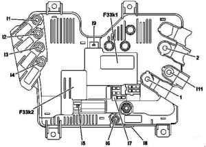
12 *
13 FOG 15 Front Fog Lights
14 *
Relay
R1 Starter Interrupt Relay
Headlight High Relay
R2 Main Relay
R3 Fuel Pump Relay
R4 Horn Relay
R5 Daytime Running Lights (DRL) Relay
R6 Cooling Fan Relay No.3
R7 Cooling Fan Relay No.2
R8 Cooling Fan Relay No.1
R9 A/C Relay
R10 A/C Relay

Passenger compartment fuse box

Mazda 626 - fuse box diagram - passenger compartment
Mazda 626 – fuse box diagram – passenger compartment
Position Description Fuse rating [A] Protected component
1 STOP 20 Brake Lights
High Mounted Brake Light
Horns
Cruise Control System
Shift-Lock System
2 ROOM 15 Courtesy Lights
Vanity Mirror Lights
Trunk Compartment Light
Audio System
Power Door Locks
Power Door Locks (with keyless entry system)
Power Antenna
Theft-Deterrent System
Central Processing System
Instrument Cluster
EC-AT Control System
Spot Lights
Interior Light
Ignition Key Illumination
Engine Control System
Ignition System
3 DOOR LOCK 30 Power Door Locks
Power Door Locks (with keyless entry system)
4 RADIO 15 Audio System
Cigarette Lighter
Power Antenna
Power Outside Mirrors
5 SUNROOF 15 Sliding Sunroof
6 TURN 15 Turn and Hazard Warning Lights
Air Bag System
7 POWER SEAT 30 Power Seat
8 METER 15 Back-Up Lights
Data Link Connector
Instrument Cluster
EC-AT Control System
Theft-Deterrent System
Central Processing System
Power Antenna
Cruise Control System
Shift-Lock System
Engine Control System (FS)
ATX Ignition System (FS)
9 HAZARD 15 Turn and Hazard Warning Lights
10 ENGINE 15 Engine Control System
MTX Fuel Control System (FS)
Ignition System
Starting System
EC-AT Control System (FS)
Coolant Fan System
Heater and Air Conditioner
Antilock Brake System
Air Bag System
Rear Window Defroster
11 POWER WINDOW 30 Power Windows
12 HEAD CLEANER 20 Headlight Cleaner
13 WIPER 20 Windshield Wiper and Washer
Heater and Air Conditioner
Condenser Fan System
Daytime Running Lights (DRL)
Engine Control System (FS)
EC-AT Control System (FS)
Ignition System (FS)
14 REAR WIPER 20 Rear Wiper & Washer
15 SPARE 15 Spare

Relay

FS

Mazda 626 - fuse box diagram - relay FS
Mazda 626 – fuse box diagram – relay FS

KL

Mazda 626 - fuse box diagram - relay KL
Mazda 626 – fuse box diagram – relay KL
Number Relay
R1 Blower Relay
R2 Headlight Relay
R3 Rear Window Defroster Relay
R4 TNS Relay
R5 Condenser Fan High Relay No.2
R6 Condenser Fan Low Relay
R7 Condenser Fan High Relay No.1

Flasher Unit

626

Mazda 626 - fuse box diagram - flasher unit
Mazda 626 – fuse box diagram – flasher unit

WARNING: Terminal and harness assignments for individual connectors will vary depending on vehicle equipment level, model, and market.