Genesis G80 (2017) – fuse box diagram
Year of production: 2017
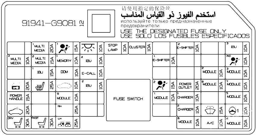
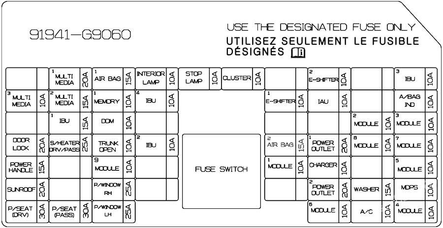
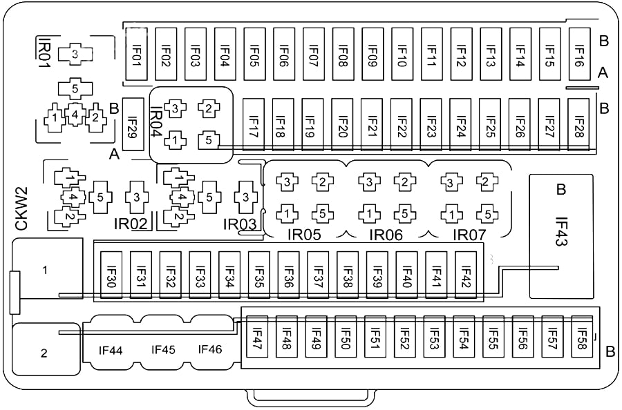
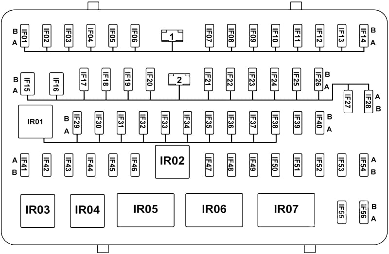
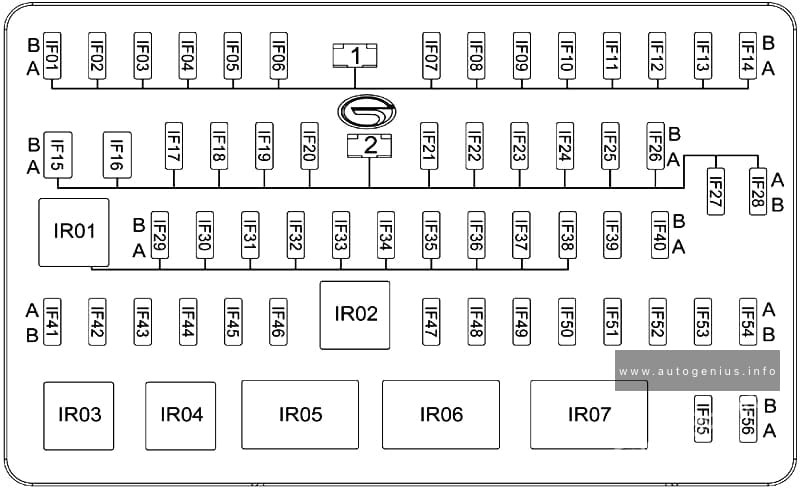
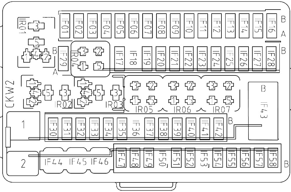
Passenger compartment fuse box
The fuse panel is located in the driver’s side panel bolster.
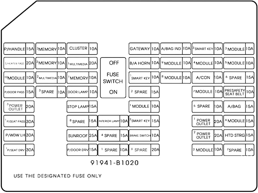
| Fuse Name | Amps | Circuit Protected |
|---|---|---|
| P/HANDLE | 15A | Steering Tilt & Telescopic Module |
| MEMORY 3 | 10A | Passenger Power Outside Mirror |
| CLUSTER | 10A | Instrument Cluster, Head-Up Display |
| GATEWAY | 10A | Gateway (IG1 (MCU)) |
| A/BAG IND | 10A | Instrument Cluster, A/C Control Module |
| SMART KEY 3 | 10A | Smart Key Control Module |
| MODULE 3 | 10A | BCM, Sport Mode Switch, Stop Lamp Switch, Driver/Passenger Door Module, Rear Door Module LH/RH |
| S/HEATER PASS | 20A | Passenger CCS Module, Passenger Seat Warmer Control Module |
| MEMORY 2 | 10A | Driver Power Outside Mirror |
| MULTIMEDIA 1 | 20A | Fuse – MULTIMEDIA 2, A/V & Navigation Head Unit |
| B/A HORN | 10A | Burglar Alarm Horn Relay |
| MODULE 9 | 10A | Multifunction Switch |
| MODULE 4 | 10A | Steering Tilt & Telescopic Module, Blind Spot Detection Radar LH/RH Crash Pad Switch, Tire Pressure Monitoring Module, Console Switch LH/RH, Front Parking Assist Sensor LH/RH, Front Parking Assist Sensor (Center), ECS Unit, Electronic Parking Brake Switch, Rear Parking Assist Sensor LH/RH, Rear Parking Assist Sensor (Center), LKAS Module |
| MODULE 5 | 10A | Multipurpose Check Connector, A/V & Navigation Head Unit, Electro Chromic Mirror, A/C Control Module, l-Box, AMP, Driver/Passenger CCS Module, Driver Power Seat Switch, Driver/Passenger Seat Warmer Control Module, Rear Seat Warmer Control Module LH/RH, Driver IMS Control Module |
| MODULE 10 | 10A | BCM |
| MULTIMEDIA 2 | 10A | Keyboard, l-Box, Front Monitor |
| MEMORY 1 | 10A | Steering Tilt & Telescopic Module, External Buzzer, BCM, Analog Clock, A/C Control Module, Tire Pressure Monitoring Module, Security Indicator, Head-Up Display, Instrument Cluster, Driver/Passenger Door Module, Rear Door Module LH/RH, Power Trunk Lid Control Module |
| SMART KEY 1 | 10A | Start/Stop Button Switch |
| MODULE 8 | 10A | BCM, Smart Key Control Module |
| A/CON | 10A | Metal Core Block (PCB #1 – Blower Relay), Ionizer CO2 Sensor, A/C Control Module |
| P/DOOR PASS | 15A | Passenger Door Latch |
| DOOR LAMP | 10A | Driver/Passenger Door Module, Rear Door Module LH/RH |
| MODULE 7 | 10A | Parking Guide Unit, Head-Up Display Sunroof, Passenger Lumbar Support Unit, Clock Spring (Steering Wheel Remote Control Switch) |
| PRESAFETY SEAT BELT | 10A | Pre-Active Seat Belt Module |
| POWER OUTLET 3 | 20A | Not Used |
| STOP LAMP | 15A | Stop Signal Electronic Module |
| MODULE 1 | 10A | Gateway (B+ (MCU)), Rain Sensor, Hazard Switch Trunk Lid Main Switch, Electronic Parking Brake Switch |
| A/BAG | 15A | SRS Control Module |
| P/SEAT PASS 1 | 30A | Passenger Power Seat Relay Box |
| INTERIOR LAMP | 10A | Room Lamp, Room Lamp LH/RH, Overhead Console Lamp, Glove Box, Front Vanity Lamp LH/RH, Driver/Passenger Foot Lamp, Trunk Room Lamp LH/RH |
| SMART KEY 2 | 15A | Smart Key Control Module |
| POWER OUTLET 1 | 20A | Front Power Outlet & Cigarette Lighter |
| MODULE 6 | 15A | Head Lamp LH/RH, Auto Hold & Drive Mode Switch, Auto Head Lamp Leveling Device Module, A/T Shift Lever IND. |
| P/WDW LH | 30A | Driver Power Window Module, Rear Door Module LH, Rear Power Window Module LH |
| SUNROOF | 25 A | Sunroof Motor |
| BRAKE SWITCH | 10A | Stop Lamp Switch, Smart Key Control Module |
| POWER OUTLET 2 | 20A | Front Power Outlet & Cigarette Lighter |
| HTD STRG | 15A | Clock Spring (Steering Wheel Heated Module) |
| P/SEAT DRV 1 | 30A | Driver IMS Control Module, Driver Power Seat Relay Box |
| P/DOOR DRV | 15A | Driver Door Latch |
| MODULE 2 | 10A | BCM, Smart Key Control Module, Overhead Console Lamp, Analog Clock, A/V & Navigation Head Unit, Keyboard, l-Box, Front Monitor, Parking Guide Unit |
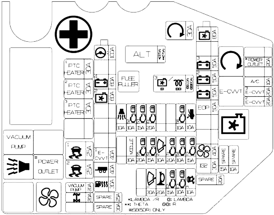
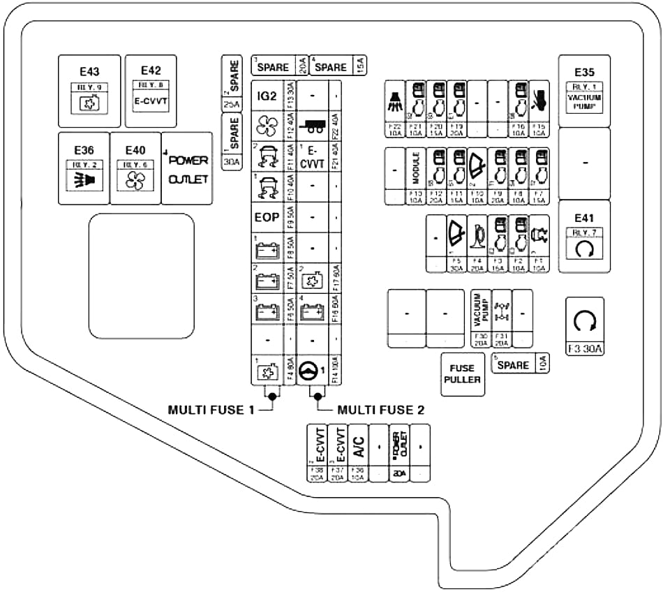
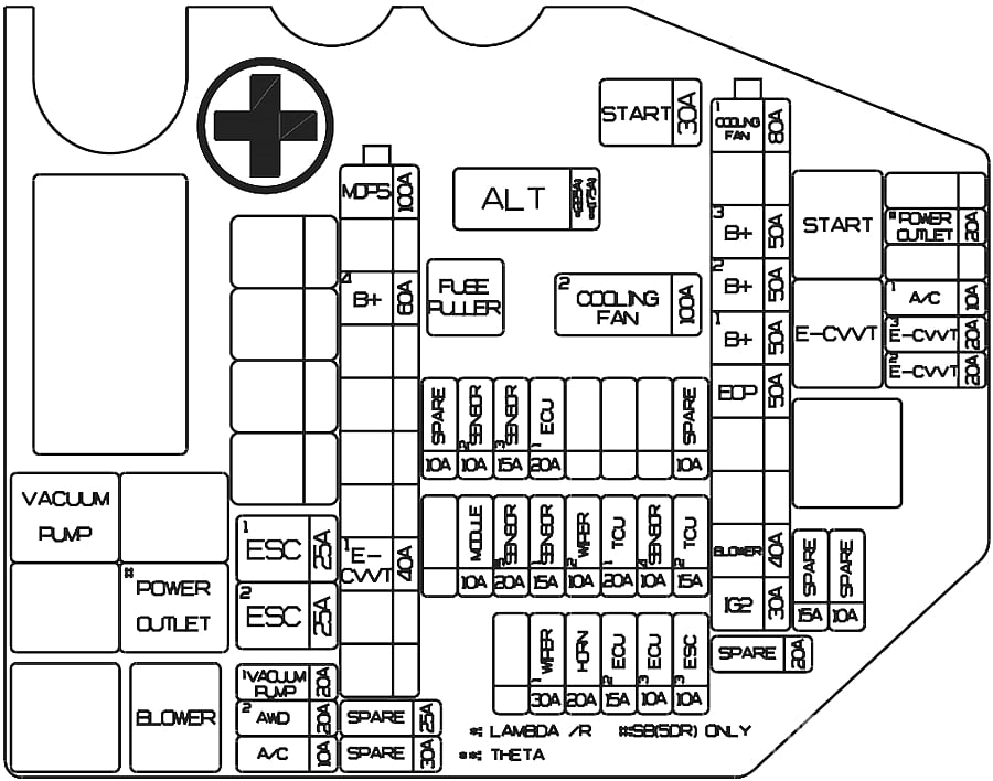
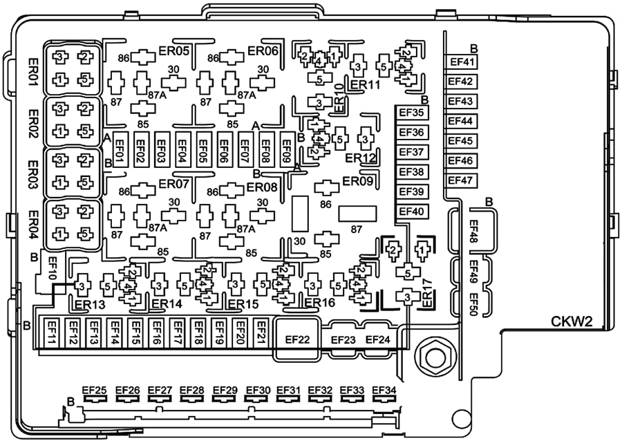
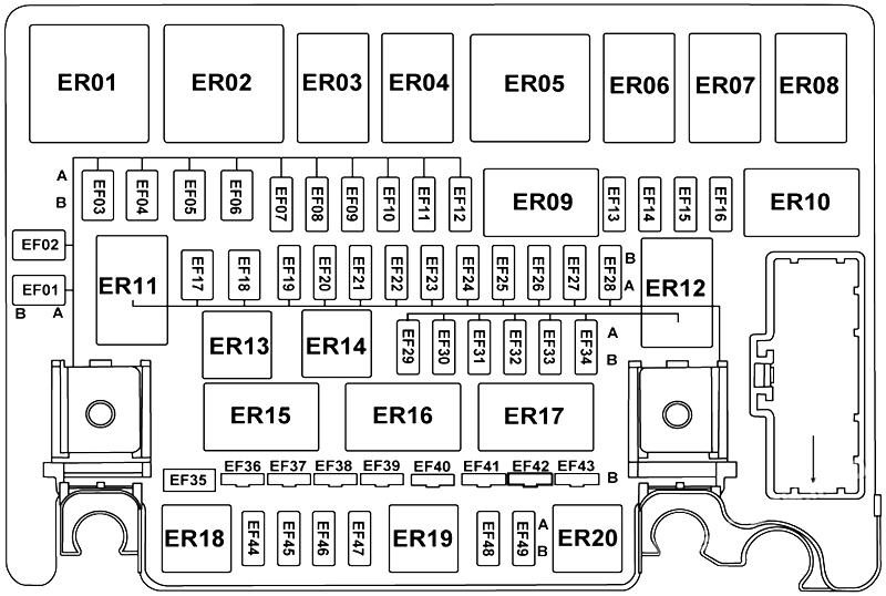
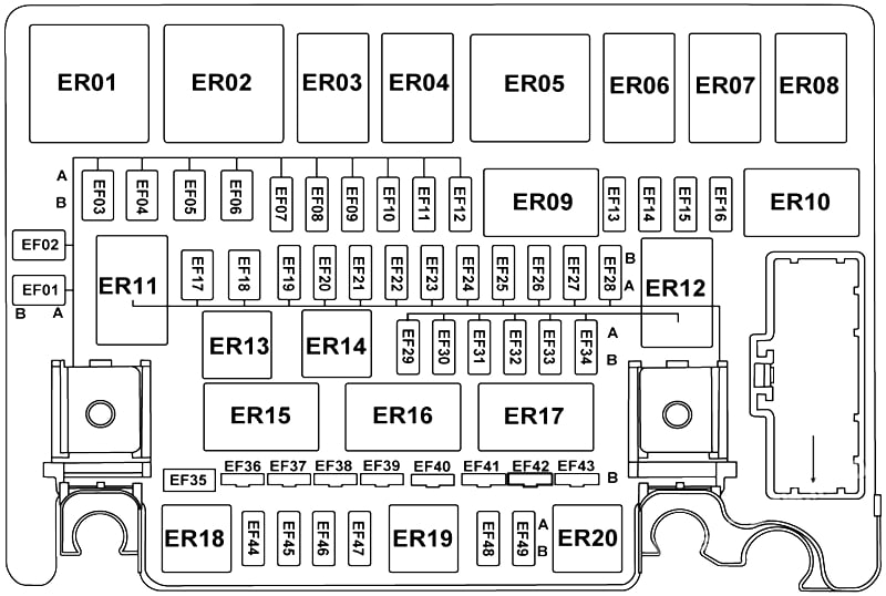
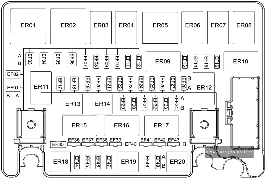
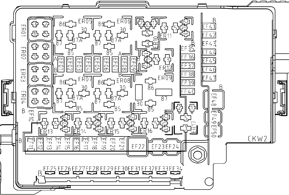
Engine Compartment Fuse Box
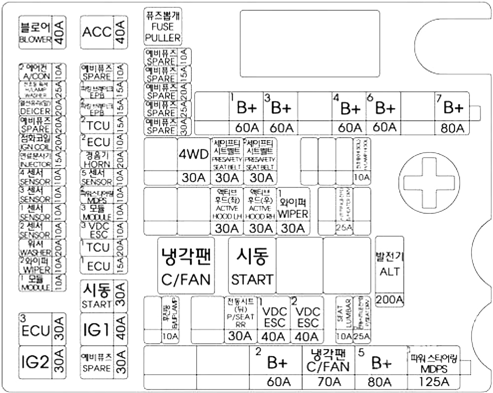
| Fuse Name | Amps | Circuit Protected |
|---|---|---|
| ALT | 200A | Alternator, Multifuse (BATT) – B+2/ B+5/ MDPS 1/ C/FAN, Fuse – P/SEAT DRV 2/ P/SEAT RR/ SEAT LUMBAR/ ESC 1/ ESC 2 |
| B+ 1 | 60A | IGPM (Fuse – BRAKE SWITCH, Leak Current Autocut Device (Fuse – INTERIOR LAMP / MULTI MEDIA 1 / MEMORY 1 / MEMORY 2 / MEMORY 3), IPS 1) |
| B+ 3 | 60A | IGPM (Fuse – SMART KEY 1/ SMART KEY 2/ MODULE 1/ B/A HORN, IPS 2/IPS 3/IPS 5/IPS 7) |
| B+ 4 | 60A | IGPM (Fuse – DOOR LAMP/ STOP LAMP, IPS 4/IPS 6) |
| B+ 6 | 60A | Metal Core Block (PCB #1 Fuse – ECU 3/ IG2/ MODULE 1) |
| B+ 7 | 80A | Metal Core Block (PCB #2 Fuse – HORN/ ACC/ EPB 1/ EPB 2) |
| B+ 2 | 60A | IGPM (Fuse – P/HANDLE/ P/WDW LH/ P/SEAT PASS 1/ S/HEATER PASS/ MODULE 10/ SUNROOF/ P/DOOR DRV/ P/DOOR PASS) |
| C/FAN | 70 A | RLY. 1 (C/Fan Relay) |
| B+ 5 | 80A | Metal Core Block (PCB #1 Fuse – BLOWER/ DEICER/ H/LAMP WASHER) |
| MDPS 1 | 125A | MDPS Unit |
| B/UP LAMP | 10A | TCM, Transmission Range Switch, Rear Combination Lamp (IN) LH/RH, Electro Chromic Mirror, A/V & Navigation Head Unit |
| P/SEAT RR | 30A | Not Used |
| ESC 1 | 40A | ESC Module, Multipurpose Check Connector |
| ESC 2 | 40A | ESC Module, Multipurpose Check Connector |
| SEAT LUMBAR | 10A | Driver/Passenger Power Seat Relay Box, Driver/Passenger Lumbar Support Unit |
| P/SEAT DRV 2 | 25A | Driver IMS Control Module, Driver Power Seat Switch, Driver Power Seat Relay Box |
| ACTIVE HOOD LH | 30A | Not Used |
| ACTIVE HOOD RH | 30A | Not Used |
| WIPER | 30A | Wiper Motor |
| S/HEATER DRV | 25A | Driver CCS Module, Driver Seat Warmer Control Module |
| 4WD | 30A | 4WD ECM |
| PRESAFETY SEAT BELT 1 | 30A | Pre-Active Seat Belt Module |
| PRESAFETY SEAT BELT 2 | 30A | Pre-Active Seat Belt Module |
| H/LAMP HI SOL | 10A | Metal Core Block (PCB #2 – Head Lamp High Solenoid Relay) |
| IG2 | 30A | IG2 Relay |
| ECU 3 | 30A | Engine Control Relay |
| MODULE 1 | 10A | 4WD ECM, Smart Cruise Control Radar, Active Air Flap |
| WIPER 2 | 10A | Metal Core Block (PCB #2 – Wiper Relay) |
| WASHER | 20A | Washer Relay |
| SENSOR 2 | 10A | ECM, Oxygen Sensor #1/#2/#3/#4 |
| SENSOR 1 | 10A | ECM, Oil Control Valve #1/#2/#3/#4, Canister Close Valve, Purge Control Solenoid Valve, Variable Intake Solenoid Valve #1/#2 |
| SENSOR 3 | 10A | ECM, Rear Junction Block (Fuel Pump Relay) |
| SENSOR 4 | 10A | C/Fan Relay, Camshaft Position Valve (G8BE) |
| INJECTOR | 15A | Injector Drive Box |
| IGN COIL | 20A | G6DJ : Condenser, Ignition Coil #1/#2/#3/#4/#5/#6, G8BE : Condenser #1/#2, Ignition Coil #1 /#2/#3/#4/#5/#6/#7/#8 |
| DEICER | 20A | Metal Core Block (PCB #2 – Front Deicer Relay) |
| H/LAMP WASHER | 25A | Head Lamp Washer Relay |
| A/CON 2 | 10A | A/C Control Module |
| BLOWER | 40A | Blower Relay |
| IG1 | 40A | IG1 Relay |
| START | 30A | E/R Junction Block (RLY. 2 – Start Relay) |
| ECU 1 | 15A | ECM, Injector Drive Box |
| TCU 1 | 20A | TCM |
| ESC 3 | 10A | ESC Module, Steering Angle Sensor |
| MODULE 3 | 10A | Smart Cruise Control Radar, Active Air Flap |
| MDPS 2 | 10A | MDPS Unit |
| SENSOR 1 | 10A | G6DJ : Oil Pressure Solenoid Velve |
| HORN | 20A | Horn Relay |
| ECU 2 | 10A | ECM, Injector Drive Box, Alternator (G8BE) |
| TCU 2 | 15A | TCM, Transmission Range Switch, 4WD ECM |
| EPB 2 | 15A | Electronic Parking Brake Module |
| EPB 1 | 15A | Electronic Parking Brake Module |
| ACC | 40A | ACC Relay |
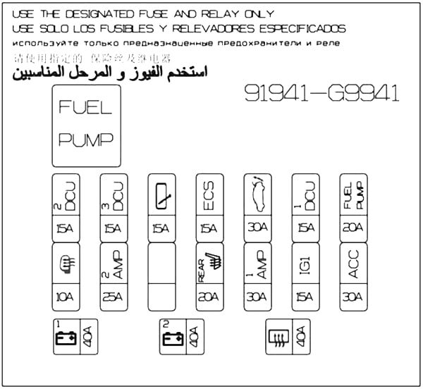
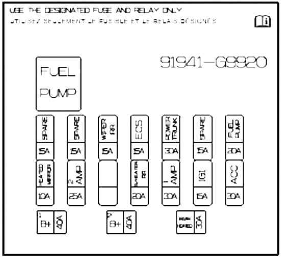
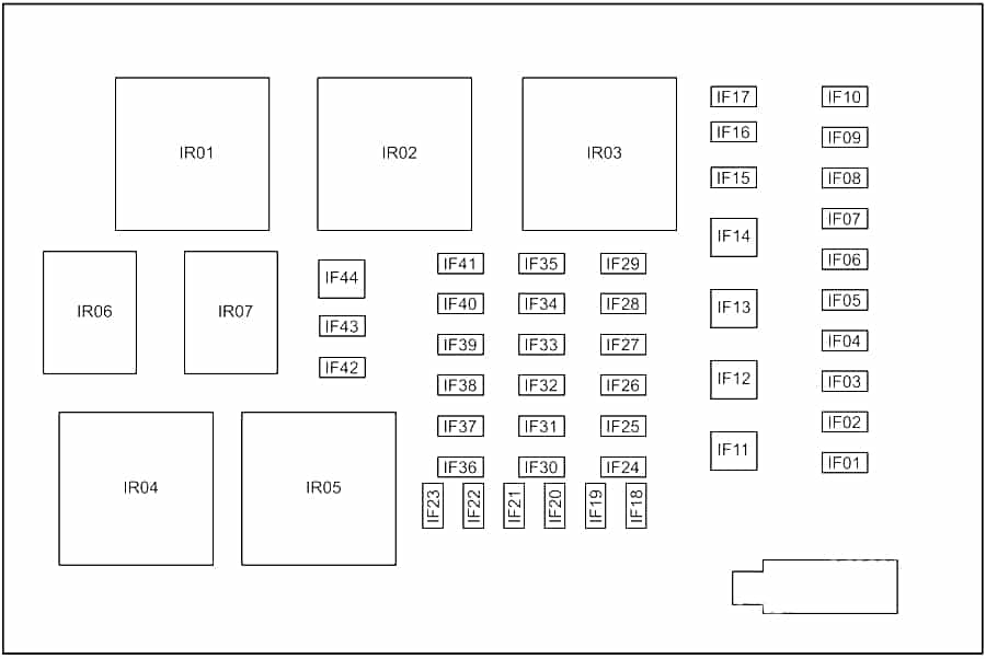
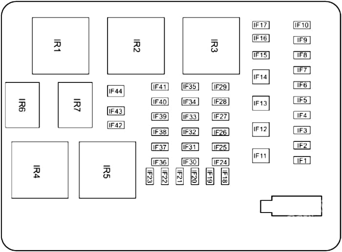
Trunk Fuse Box Diagra
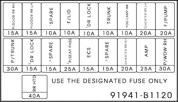
| Fuse Name | Amps | Circuit Protected |
|---|---|---|
| P/TRUNK | 30A | Power Trunk Lid Control Module |
| P/DOOR RR RH | 15A | Rear Door Latch RH |
| DR LOCK 2 | 15A | Passenger Door Module |
| P/DOOR RR LH | 15A | Rear Door Latch LH |
| SPARE 3 | 15A | Spare Fuse |
| SPARE 1 | 10A | Spare Fuse |
| P/SEAT PASS 2 | 25A | Passenger Power Seat Relay Box |
| F/LID | 10A | Fuel Lid Open Relay, Crash Pad Switch |
| ECS | 15A | ECS Unit |
| DR LOCK 1 | 10A | Driver Door Module |
| SPARE 5 | 15A | Spare Fuse |
| TRUNK | 10A | Trunk Lid Relay, Power Trunk Module Buzzer |
| S/HEATER RR RH | 20A | Rear Seat Warmer Control Module RH |
| FOG LAMP RR | 10A | Not Used |
| AMP | 25A | AMP |
| S/HEATER RR LH | 20A | Rear Seat Warmer Control Module LH |
| P/WDW RH | 30A | Passenger Power Window Module, Rear Power Window Module RH |
| F/PUMP | 20A | Fuel Pump Relay |
| RR HTD | 40A | Rear Defogger Relay |
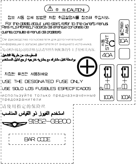
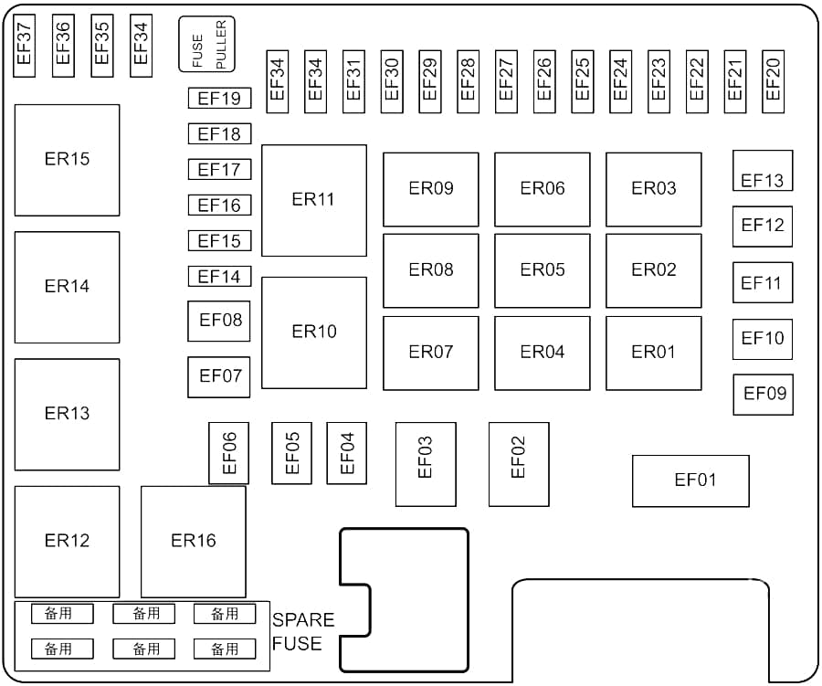
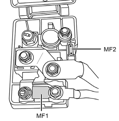
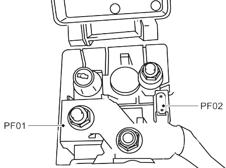
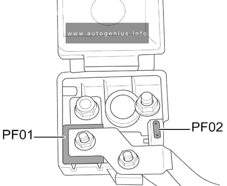
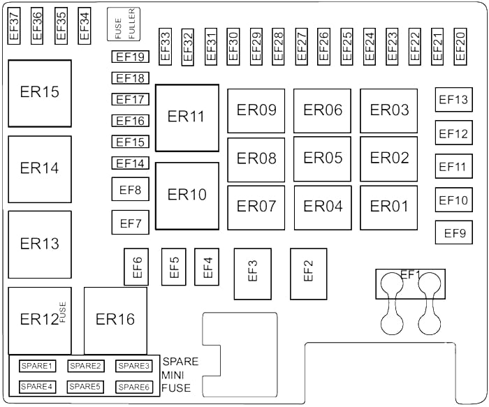
Battery box
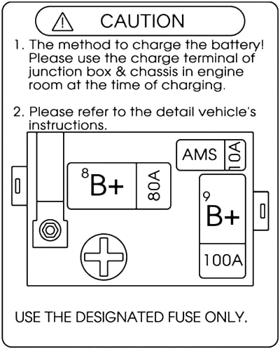
| Fuse Name | Fuse rating | Circuit Protected |
|---|---|---|
| B+ 9 | 100A | Rear Junction Block (Fuse – RR HTD/ P/TRUNK/ ECS/ F/LID/ P/DOOR RR RH/ DR LOCK 2/ P/DOOR RR LH/ AMP/ P/SEAT PASS 2/ DR LOCK 1/TRUNK/ S/HEATER RR RH/ S/HEATER RR LH/ P/WDW RH/ F/PUMP) |
| B+ 8 | 80A | Metal Core Block (PCB #2 Fuse – TCU/ ECU 1/ START/ IG 1) |
| AMS | 10A | Battery Sensor |