Front right seat connector / rear right seat connector
IF7
7.5A
Front left courtesy light / front right courtesy light / rear left courtesy light / rear right courtesy light / power sunshade / rear-view mirror folding relay / rear-view mirror unfolding relay
IF8
7.5A
TPMS control unit / EPB switch / high brake light
IF9
20A
Front AUDIO control unit / rear AUDIO control unit
IF10
10A
Brake switch / TCU / gearshift lever
IF11
30A
DCDC converter
IF12
30A
Right sliding door control unit
IF13
20A
Body control module (front right window regulator motor / rear right window regulator motor power supply) / front right window regulator motor / rear right window regulator motor
IF14
30A
IG1 relay / ACC relay
IF15
25A
Front left seat connector / rear left seat connector
IF16
7.5A
OBD diagnosis interface
IF17
10A
Instrument cluster / front central console panel / T-Box control unit / memory seat control unit / panorama parking control unit
IF18
30A
Electric hatchback door control unit
IF19
15A
Body control module (wiper cleaning motor / rear wiper motor power supply)
IF20
20A
Front left window regulator control unit / front left window regulator switch
IF21
10A
Rear left seat connector / rear right seat connector
IF22
20A
Body control module (door lock power supply)
IF23
30A
Left sliding door control unit
IF24
25A
Front cigarette lighter / rear cigarette lighter / rear 12V power interface
IF25
7.5A
PEPS control unit / body control module
IF26
10A
Memory seat control unit / rear AUDIO control unit / rear-view mirror adjustment switch / front AUDIO control unit
IF27
—
—
IF28
7.5A
Anion generator
IF29
10A
Air quality sensor / front blower relay / rear blower relay / interior rear-view mirror / PEPS control unit / defroster relay
IF30
7.5A
Lane departure warning control unit / headlight height adjustment switch / left combination headlight / right combination headlight / front collision warning control module / panorama parking control unit / reversing radar control unit / automatic parking control unit
IF31
10A
Auxiliary instrument panel switch group / sunroof control unit / sunroof sunshade / rain and light sensor / front central console panel / front A/C control panel / automatic headlight control unit / T-BOX control unit / instrument cluster / front A/C control unit / rear A/C control panel / front left seat connector / rear left seat connector / rear right seat connector / right sliding door control unit / rear A/C control unit / electric hatchback door control unit / left sliding door control unit / left instrument panel switch group
IF32
7.5A
Steering angular speed sensor / TPMS control unit / EPS control unit / brake switch / ESP and EPB control unit
IF33
7.5A
Gateway control unit / body control module / PEPS control unit / DCDC converter
IF34
10A
Airbag control unit
IF35
7.5A
Gearshift lever / engine control unit / TCU
IF36
20A
Body control module (rear left window regulator switch) / rear left window regulator motor
IF37
7.5A
PEPS control unit
IF38
7.5A
Front left door antenna / front right door antenna / PEPS control unit
IF39
7.5A
Intelligent atmosphere light control module / A/C control unit / rear A/C control panel / front A/C control panel / display screen / automatic headlight control unit / front left seat connector / front right seat connector / right sliding door control unit / rear A/C control unit / left sliding door control unit / electric hatchback door closing switch / electric hatchback door control unit / trunk light
IF40
7.5A
Smartphone wireless charging module / inverter / USB charging port
IF41
15A
Body control module
IF42
—
—
IF43
7.5A
Left rear-view mirror heater / right rear-view mirror heater
IF44
30A
Rear defogging heater
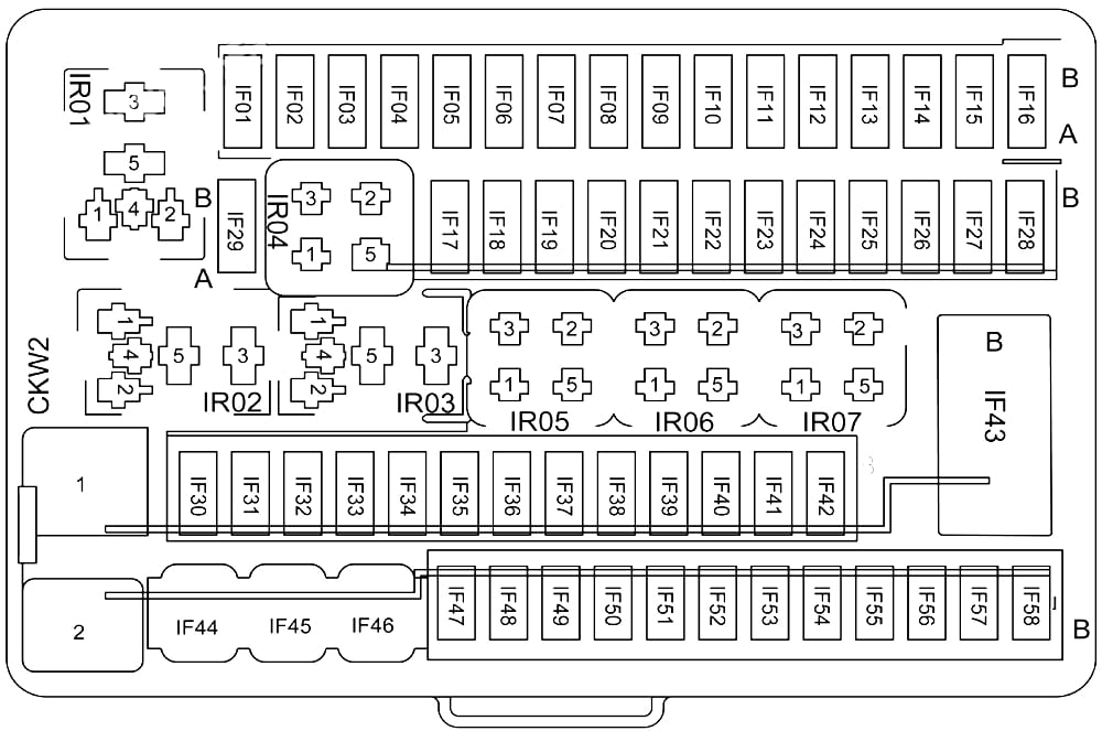
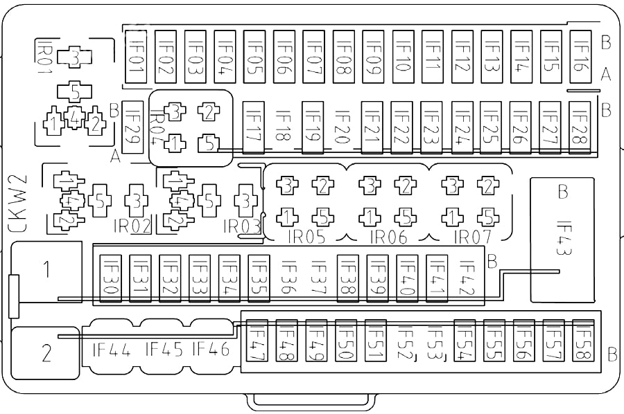
IR01
—
IG2 relay
IR02
—
ACC relay
IR03
—
IG1 relay
IR04
—
—
IR05
—
Defroster relay
IR06
—
Rear-view mirror folding relay
IR07
—
Rear-view mirror unfolding relay
IF52
7.5A
Automatic headlight control unit
IF53
7.5A
Front left door handle switch
IF54
7.5A
A/C control unit / PM2.5 sensor
IF55
15A
Body Control Module
IF56
7.5A
Front A/C control panel / rear A/C control panel / AUDIO display / instrument cluster
Front right seat connector / rear right seat connector
IF7
7.5A
Front left courtesy light / front right courtesy light / rear left courtesy light / rear right courtesy light / power sunshade / rear-view mirror folding relay / rear-view mirror unfolding relay
IF8
7.5A
TPMS control unit / EPB switch / high brake light
IF9
20A
Front AUDIO control unit / rear AUDIO control unit
IF10
10A
Brake switch / TCU / gearshift lever
IF11
30A
DCDC converter
IF12
30A
Right sliding door control unit
IF13
20A
Body control module (front right window regulator motor / rear right window regulator motor power supply) / front right window regulator motor / rear right window regulator motor
IF14
30A
IG1 relay / ACC relay
IF15
25A
Front left seat connector / rear left seat connector
IF16
7.5A
OBD diagnosis interface
IF17
10A
Instrument cluster / front central console panel / T-Box control unit / memory seat control unit / panorama parking control unit
IF18
30A
Electric hatchback door control unit
IF19
15A
Body control module (wiper cleaning motor / rear wiper motor power supply)
IF20
20A
Front left window regulator control unit / front left window regulator switch
IF21
10A
Rear left seat connector / rear right seat connector
IF22
20A
Body control module (door lock power supply)
IF23
30A
Left sliding door control unit
IF24
25A
Front cigarette lighter / rear cigarette lighter / rear 12V power interface
IF25
7.5A
PEPS control unit / body control module
IF26
10A
Memory seat control unit / rear AUDIO control unit / rear-view mirror adjustment switch / front AUDIO control unit
IF27
—
—
IF28
7.5A
Anion generator
IF29
10A
Air quality sensor / front blower relay / rear blower relay / interior rear-view mirror / PEPS control unit / defroster relay
IF30
7.5A
Lane departure warning control unit / headlight height adjustment switch / left combination headlight / right combination headlight / front collision warning control module / panorama parking control unit / reversing radar control unit / automatic parking control unit
IF31
10A
Auxiliary instrument panel switch group / sunroof control unit / sunroof sunshade / rain and light sensor / front central console panel / front A/C control panel / automatic headlight control unit / T-BOX control unit / instrument cluster / front A/C control unit / rear A/C control panel / front left seat connector / rear left seat connector / rear right seat connector / right sliding door control unit / rear A/C control unit / electric hatchback door control unit / left sliding door control unit / left instrument panel switch group
IF32
7.5A
Steering angular speed sensor / TPMS control unit / EPS control unit / brake switch / ESP and EPB control unit
IF33
7.5A
Gateway control unit / body control module / PEPS control unit / DCDC converter
IF34
10A
Airbag control unit
IF35
7.5A
Gearshift lever / engine control unit / TCU
IF36
20A
Body control module (rear left window regulator switch) / rear left window regulator motor
IF37
7.5A
PEPS control unit
IF38
7.5A
Front left door antenna / front right door antenna / PEPS control unit
IF39
7.5A
Intelligent atmosphere light control module / A/C control unit / rear A/C control panel / front A/C control panel / display screen / automatic headlight control unit / front left seat connector / front right seat connector / right sliding door control unit / rear A/C control unit / left sliding door control unit / electric hatchback door closing switch / electric hatchback door control unit / trunk light
IF40
7.5A
Smartphone wireless charging module / inverter / USB charging port
IF41
15A
Body control module
IF42
—
—
IF43
7.5A
Left rear-view mirror heater / right rear-view mirror heater
IF44
30A
Rear defogging heater
IR01
—
IG2 relay
IR02
—
ACC relay
IR03
—
IG1 relay
IR04
—
—
IR05
—
Defroster relay
IR06
—
Rear-view mirror folding relay
IR07
—
Rear-view mirror unfolding relay
IF52
7.5A
Automatic headlight control unit
IF53
7.5A
Front left door handle switch
IF54
7.5A
A/C control unit / PM2.5 sensor
IF55
15A
Body Control Module
IF56
7.5A
Front A/C control panel / rear A/C control panel / AUDIO display / instrument cluster
Power sunroof control unit / panorama sunroof control unit / panorama sunroof sunshade motor
IF04
—
—
IF05
20A
Body control module (front right window regulator)
IF06
20A
Body control module (front left window regulator)
IF07
20A
Body control module (rear right window regulator)
IF08
20A
Body control module (rear left window regulator)
IF09
7.5A
Smartphone wireless charging module
IF10
—
—
IF11
15A
Body control module (windshield washer and rear wiper motor)
IF12
10A
Rear-view mirror folding
IF13
—
—
IF14
—
—
IF15
—
—
IF16
30A
Instrument panel fuse box
IF17
7.5A
OBD Diagnosis Interface
IF18
20A
Body control module (main light)
IF19
7.5A
Gateway module
IF20
7.5A
Gearshift module
IF21
10A
Body control module (turn signal)
IF22
—
—
IF23
7.5A
PEPS control unit / Ignition switch / ESCL
IF24
20A
Body control module (main light)
IF25
7.5A
High brake light / EPB switch
IF26
20A
Body control module (door lock)
IF27
—
—
IF28
SHUNT
Divider
IF29
10A
SRS control unit
IF30
7.5A
Engine control unit / AT control unit
IF31
7.5A
Gateway module/ body control module / PEPS control unit
IF32
—
—
IF33
7.5A
Steering angular speed sensor / EPS control unit/gearshift module
IF34
7.5A
Brake switch / ESP and EPB control module
IF35
7.5A
Parking sensor control unit / panoramic parking control unit /rear A/C control panel / seat heating
IF36
7.5A
Air quality sensor/anion generator
IF37
7.5A
Front left combination light (height adjustment motor) / front right combination light (height adjustment motor) / headlight height adjustment switch / automatic headlight control unit
IF38
7.5A
Rain and light sensor / power sunroof control unit / panoramic sunroof control unit / front A/C control panel / A/C control unit / instrument cluster / AUDIO control unit
IF39
15A
AT control unit
IF40
15A
AUDIO control unit
IF41
7.5A
Body control module / PEPS control unit
IF42
7.5A
USB charging port 1 / USB charging port 2
IF43
25A
Right trunk 12V power supply interface
IF44
7.5A
AUDIO control unit / rear-view mirror adjustment switch
IF45
25A
Front 12V power supply interface
IF46
—
—
IF47
7.5A
Front blower relay / rear blower relay / defogging relay / PEPS control unit / electric anti-glare interior rear-view mirror
IF48
—
—
IF49
—
—
IF50
7.5A
Body control module / PEPS control unit / engine control unit / starter relay 1 / starter relay 2
IF51
7.5A
Panoramic parking control unit
IF52
7.5A
Automatic headlight control unit
IF53
7.5A
Front left door handle switch
IF54
7.5A
A/C control unit / PM2.5 sensor
IF55
15A
Body Control Module
IF56
7.5A
Front A/C control panel / rear A/C control panel / AUDIO display / instrument cluster
IR01
—
IG1 relay
IR02
—
IG2 relay
IR03
—
—
IR04
—
—
IR05
—
ACC relay
IR06
—
Rear-view mirror folding relay
IR07
—
Rear-view mirror unfolding relay
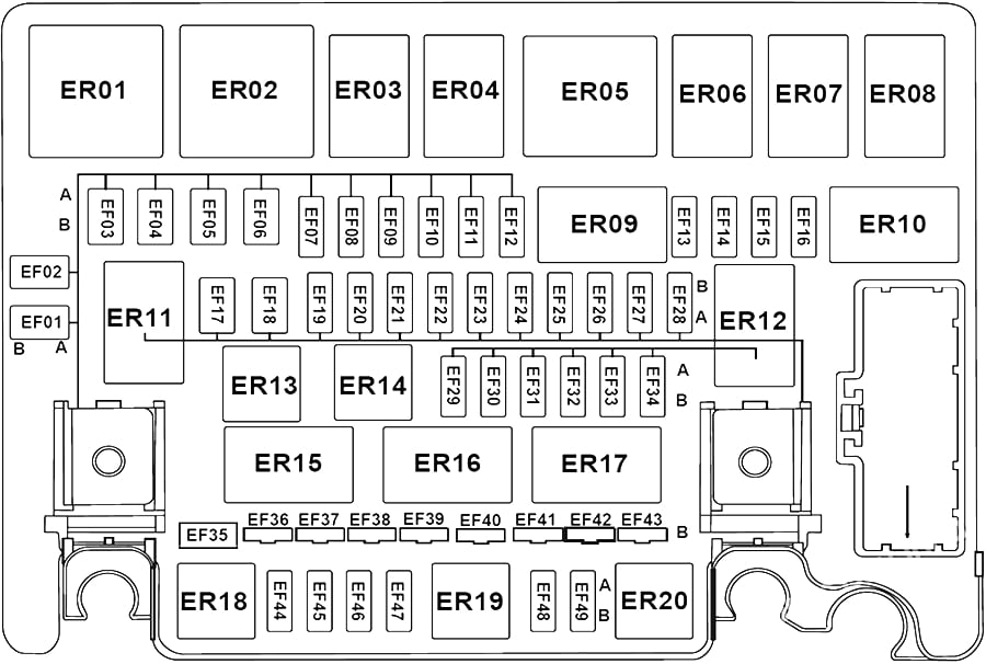
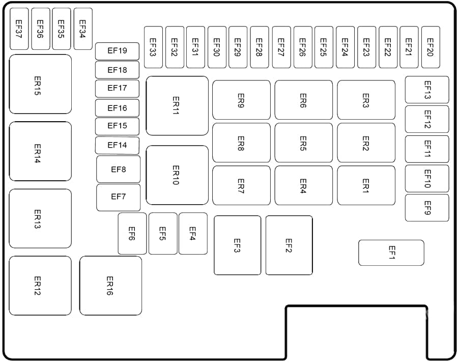
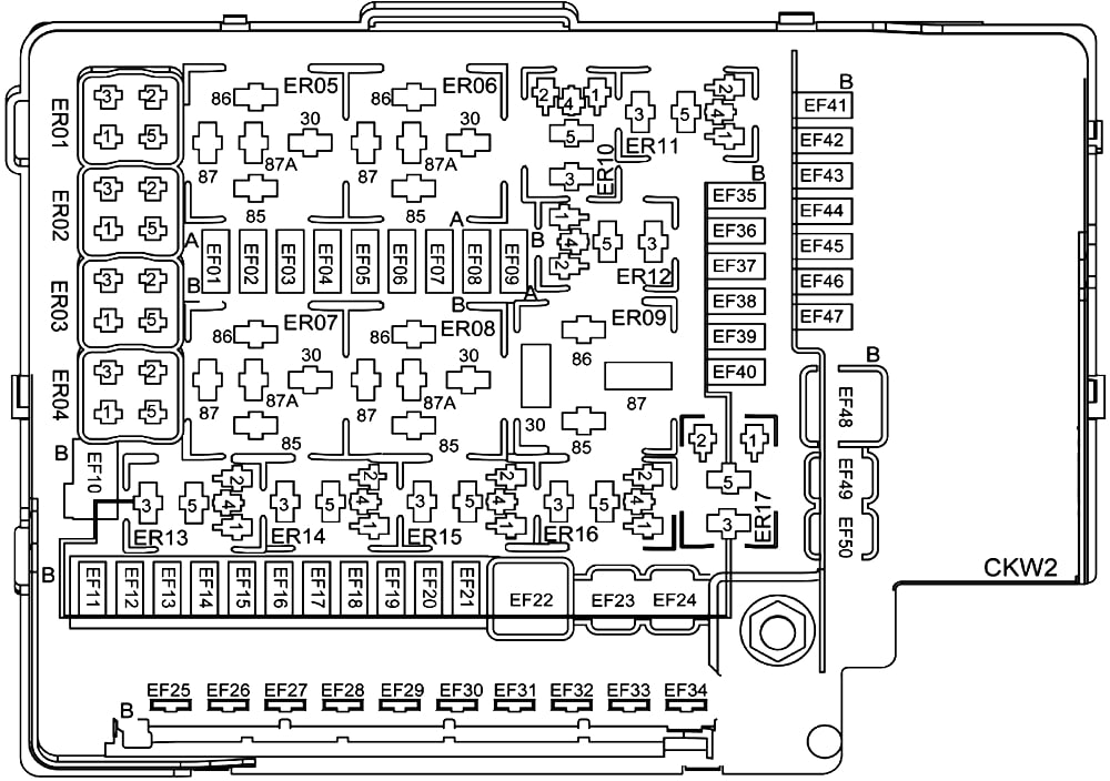
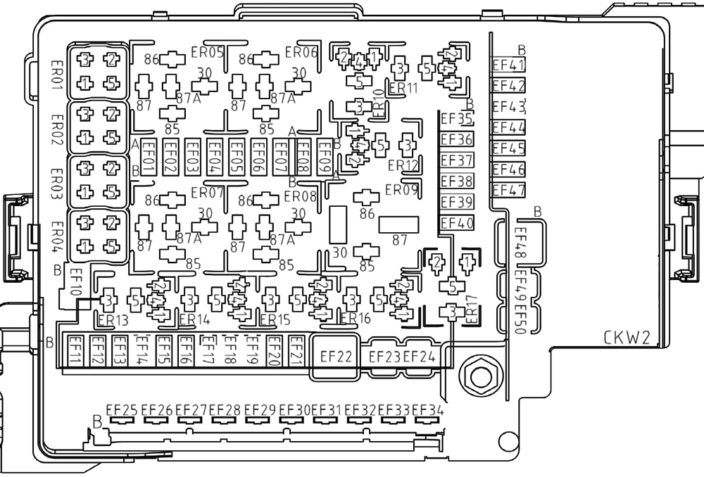
Engine Compartment Fuse Box
GAC GM6 – fuse box diagram – engine compartment
№
Amps
Function
EF01
—
—
EF02
—
—
EF03
40A
Rear Blower
EF04
40A/60A
ESP and EPB control module
EF05
—
—
EF06
—
—
EF07
7.5A
A/C compressor
EF08
—
—
EF09
—
—
EF10
20A
Seat Heating
EF11
20A
High beam relay (high beam)
EF12
—
—
EF13
15A
Front Left Low Beam
EF14
15A
Front Right Low Beam
EF15
7.5A
Engine control unit
EF16
7.5A
Left rear-view mirror defogger / right rear-view mirror defogger
EF17
—
—
EF18
40A
ACC relay / ignition switch / IG1 relay
EF19
7.5A
Low Beam Relay
EF20
—
—
EF21
—
—
EF22
—
—
EF23
20A
Fuel pump
EF24
25A
Wiper
EF25
7.5A
Brake switch / main relay / starter relay 1 / starter relay 2 / engine control unit / ESP and EPB control module
Power sunroof control unit / panorama sunroof control unit / panorama sunroof sunshade motor
IF04
—
—
IF05
20A
Body control module (front right window regulator)
IF06
20A
Body control module (front left window regulator)
IF07
20A
Body control module (rear right window regulator)
IF08
20A
Body control module (rear left window regulator)
IF09
7.5A
Smartphone wireless charging module
IF10
—
—
IF11
15A
Body control module (windshield washer and rear wiper motor)
IF12
10A
Rear-view mirror folding
IF13
—
—
IF14
—
—
IF15
—
—
IF16
30A
Instrument panel fuse box
IF17
7.5A
OBD Diagnosis Interface
IF18
20A
Body control module (main light)
IF19
7.5A
Gateway module
IF20
7.5A
Gearshift module
IF21
10A
Body control module (turn signal)
IF22
—
—
IF23
7.5A
PEPS control unit / Ignition switch / ESCL
IF24
20A
Body control module (main light)
IF25
7.5A
High brake light / EPB switch
IF26
20A
Body control module (door lock)
IF27
—
—
IF28
SHUNT
Divider
IF29
10A
SRS control unit
IF30
7.5A
Engine control unit / AT control unit
IF31
7.5A
Gateway module/ body control module / PEPS control unit
IF32
—
—
IF33
7.5A
Steering angular speed sensor / EPS control unit/gearshift module
IF34
7.5A
Brake switch / ESP and EPB control module
IF35
7.5A
Parking sensor control unit / panoramic parking control unit /rear A/C control panel / seat heating
IF36
7.5A
Air quality sensor/anion generator
IF37
7.5A
Front left combination light (height adjustment motor) / front right combination light (height adjustment motor) / headlight height adjustment switch / automatic headlight control unit
IF38
7.5A
Rain and light sensor / power sunroof control unit / panoramic sunroof control unit / front A/C control panel / A/C control unit / instrument cluster / AUDIO control unit
IF39
15A
AT control unit
IF40
15A
AUDIO control unit
IF41
7.5A
Body control module / PEPS control unit
IF42
7.5A
USB charging port 1 / USB charging port 2
IF43
25A
Right trunk 12V power supply interface
IF44
7.5A
AUDIO control unit / rear-view mirror adjustment switch
IF45
25A
Front 12V power supply interface
IF46
—
—
IF47
7.5A
Front blower relay / rear blower relay / defogging relay / PEPS control unit / electric anti-glare interior rear-view mirror
IF48
—
—
IF49
—
—
IF50
7.5A
Body control module / PEPS control unit / engine control unit / starter relay 1 / starter relay 2
IF51
7.5A
Panoramic parking control unit
IF52
7.5A
Automatic headlight control unit
IF53
7.5A
Front left door handle switch
IF54
7.5A
A/C control unit / PM2.5 sensor
IF55
15A
Body Control Module
IF56
7.5A
Front A/C control panel / rear A/C control panel / AUDIO display / instrument cluster
IR01
—
IG1 relay
IR02
—
IG2 relay
IR03
—
—
IR04
—
—
IR05
—
ACC relay
IR06
—
Rear-view mirror folding relay
IR07
—
Rear-view mirror unfolding relay
Engine Compartment Fuse Box
GAC GN6 – fuse box diagram – engine compartment
№
Amps
Function
EF01
—
—
EF02
—
—
EF03
40A
Rear Blower
EF04
40A/60A
ESP and EPB control module
EF05
—
—
EF06
—
—
EF07
7.5A
A/C compressor
EF08
—
—
EF09
—
—
EF10
20A
Seat Heating
EF11
20A
High beam relay (high beam)
EF12
—
—
EF13
15A
Front Left Low Beam
EF14
15A
Front Right Low Beam
EF15
7.5A
Engine control unit
EF16
7.5A
Left rear-view mirror defogger / right rear-view mirror defogger
EF17
—
—
EF18
40A
ACC relay / ignition switch / IG1 relay
EF19
7.5A
Low Beam Relay
EF20
—
—
EF21
—
—
EF22
—
—
EF23
20A
Fuel pump
EF24
25A
Wiper
EF25
7.5A
Brake switch / main relay / starter relay 1 / starter relay 2 / engine control unit / ESP and EPB control module
Sunroof sunshade motor / panorama sunroof control unit / electric sunroof control unit
IF07
7.5A
OBD (on-board diagnostic) interface
IF08
10A
IG2 relay
IF09
—
—
IF10
—
—
IF11
30A
Left front window regulator motor / body control unit / right rear window regulator motor (w/o express-up and down feature) / right rear window regulator motor (with express-up and down feature) / body control unit
IF12
30A
Front right window regulator motor (w/express-up and down feature) / body control unit / left rear window regulator motor (w/express-up and down feature) / left rear window regulator motor (w/o express-up and down feature)
IF13
30A
Gearshift lever module
IF14
30A
Gearshift lever module
IF15
20A
Body control unit
IF16
7.5A
Keyless start and smart entry system control unit / gateway control unit
IF17
7.5A
Gateway control unit / body control unit / keyless start and smart entry system control unit
IF18
10A
Body control unit
IF19
15A
Body control unit
IF20
7.5A
Keyless start and smart entry system control unit
IF21
20A
Body control unit
IF22
7.5A
High-mounted stop lamp
IF23
20A
Body control unit
IF24
—
—
IF25
10A
Mobile phone wireless charging module / USB 5V power supply / left front seat connector C / rear sunshade / amplifier module / audio control unit (w/integrated T-BOX function) / audio control unit (USB 2 only) / exterior rearview mirror adjustment switch (w/o memory)
IF26
7.5A
Body control unit / keyless start and smart entry system control unit
IF27
—
—
IF28
—
—
IF29
—
—
IF30
7.5A
Left front combination lamp / right front combination lamp / headlamp leveling switch / Headlamp automatic adjustment control unit
IF31
7.5A
Electric sunroof control unit / right front seat connector A / rain light sensor / panoramic sunroof control unit / negative ion generato / A/C control panel / A/C control unit / air quality sensor / rear central control panel / front central control panel
IF32
7.5A
Reversing radar control unit / panorama parking control unit / automatic parking control unit / lane departure warning module / forward radar module / audio control unit (w/integrated T-BOX function) / instrument cluster / T-BOX control unit
IF33
7.5A
Steering angular velocity sensor / electric power steering control unit / gearshift lever module
IF34
10A
Airbag control unit
IF35
7.5A
Electronic stability and parking control module / brake switch / engine control unit / automatic transmission control unit
IF36
7.5A
Panoramic parking control unit / blind spot detection auxiliary control unit / blind zone detection main control unit / lane departure warning module / forward radar module
IF37
7.5A
Headlamp automatic adjustment control unit / T-BOX control unit
IF38
7.5A
Right front door handle switch / left front door handle switch
IF39
15A
Mobile phone wireless charging module / left front seat connector C / A/C control unit / left front door centralized control switch / PM2.5 sensor
IF40
—
—
IF41
—
—
IF42
—
—
IF43
7.5A
Right exterior rearview mirror / left exterior rearview mirror
IF44
30A
Rear windshield defogger
IR01
—
IG2 relay
IR02
—
ACC relay
IR03
—
IG1 relay
IR04
—
Fuel tank cap lock relay
IR05
ACC
Defogger relay
IR06
—
Rearview mirror folding relay
IR07
—
Rearview mirror unfolding relay
IF52
7.5A
T-BOX ECU / Mobile phone WCM / Smart Bluetooth module
IF53
7.5A
Left front door handle antenna / right front door handle antenna
IF54
7.5A
Intelligent ambient light control unit / HVAC control unit / left front door centralized control switch / PM2.5 sensor
IF55
15A
BCM (main lamps)
IF56
7.5A
HCP / rear central control panel / AV display / front central control panel
Power sunroof control unit / panorama sunroof control unit / panorama sunroof sunshade motor
IF04
—
—
IF05
20A
BCM (right front door window regulator motor) / right front door window regulator motor (with express-up & down)
IF06
20A
Left front door window regulator motor
IF07
20A
BCM (right rear door window regulator motor) / right rear door window regulator motor (with express-up & down)
IF08
20A
BCM (left rear door window regulator motor) / left rear door window regulator motor (with express-up & down)
IF09
15A
Amplifier module
IF10
15A
Amplifier module
IF11
15A
BCM (wiper and washer)
IF12
10A
MSM / rearview mirror folding relay
IF13
—
—
IF14
—
—
IF15
30A
DC-DC converter
IF16
30A
DC-DC converter / instrument panel PDU
IF17
7.5A
OBD DLC
IF18
20A
BCM (main lamps)
IF19
7.5A
GWM
IF20
30A
GSM
IF21
10A
BCM (turn signal lamp)
IF22
30A
GSM
IF23
7.5A
PEPS ECU
IF24
20A
BCM
IF25
7.5A
High-mounted stop lamp
IF26
20A
BCM (door lock)
IF27
10A
Fuel filler cap lock relay/fuel filler cap lock motor
IF28
SHUNT
Shorting link
IF29
10A
SRS ECU
IF30
7.5A
ECM/TCU
IF31
7.5A
GWM / BCM / PEPS ECU
IF32
—
—
IF33
7.5A
SAS / electric power steering control unit / GSM
IF34
7.5A
Brake switch / ESPI
IF35
7.5A
RPA ECU / brake switch / ESPI / SVM ECU / APA control unit / LDW ECU / MRR / ACU / T-B0X control unit / DC-DC converter
IF36
7.5A
IPC
IF37
7.5A
Left front combination lamp (adjustment motor) / right front combination lamp (adjustment motor) / air quality sensor / ALS switch / negative ion generator
IF38
7.5A
RLS / panorama sunroof ECU / power sunroof control unit / HVAC control unit / HCP / left front seat heating / left instrument panel switch block (ENGINE START/STOP button) / rear central control panel / front central control panel
Trunk light / front left courtesy light / front right courtesy light / rear-view mirror folding relay / rear-view mirror unfolding relay
IF8
15A
Body Control Module
IF9
–
–
IF10
–
–
IF11
–
–
IF12
20A
Body control module (front left window regulator power, rear left window regulator power)
IF13
20A
Body control module (front right window regulator power, rear right window regulator power)
IF14
30A
IG1 relay / ACC relay / lgnition switch
IF15
20A
Front left seat connector (seat adjustment power)
IF16
7.5A
OBD Diagnostic Interface
IF17
–
–
IF18
10A
Instrument cluster / T-BOX control unit / panorama parking control unit
IF19
15A
Body control module (wiper cleaning power)
IF20
20A
Front left seat connector (seat heating power)
IF21
–
–
IF22
20A
Body control module (door lock power supply)
IF23
–
–
IF24
20A
Cigarette Lighter
IF25
7.5A
Body control module / PEPS control unit
IF26
10A
AUDIO control unit / rear-view mirror adjustment switch
IF27
7.5A
Smartphone wireless charging module / USB charging port
IF28
–
–
IF29
7.5A
Blower relay / electronic anti-glare rear-view mirror / PEPS control unit / defogging relay
IF30
7.5A
Gateway control unit / body control module / PEPS control unit
IF31
10A
Sunroof control unit / rain and light sensor / front central console panel / T-BOX control unit / instrument cluster / A/C control unit / front left seat connector / left dashboard switch group
IF32
7.5A
Steering angular speed sensor / EPB control unit / TPMS control unit / EPS control unit / ABS/ESP control unit
IF33
7.5A
Front left combination light (adjustment motor) / front right combination light (adjustment motor) / reversing radar control unit / panorama parking control unit / headlight height adjustment switch / anion generator / A/C control panel
IF34
10A
Supplemental Restraint System Control Unit
IF35
7.5A
Shift lever / 4AT control unit / 6AT control unit / brake switch / engine control unit
IF36
7.5A
High brake light / TPMS control unit / EPB switch
IF37
7.5A
PEPS control unit / ESCL
IF38
7.5A
Ignition switch / PEPS control unit / PEPS immobilizer coil
IF39
10A
Front central console panel / A/C control unit / A/C control panel
IF40
7.5A
Body control module / starter relay 1 / starter relay 2 / engine control unit
IF41
–
–
IF42
–
–
IF43
7.5A
Left rear-view mirror heater / right rear-view mirror heater
The Cadillac Lyriq, a battery-electric mid-size luxury crossover, has been available from 2022 to the present. In this guide, you will find fuse box diagrams for the 2022, 2023, and 2024 Cadillac Lyriq models, along with information on the locations of the fuse panels inside the vehicle and the assignment of each fuse (fuse layout).
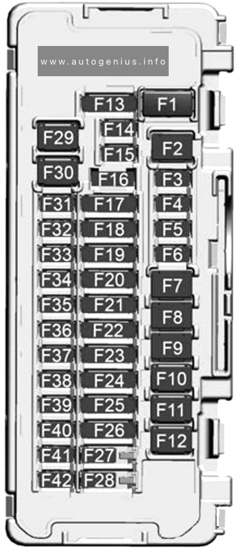
Passenger compartment Fuse Box
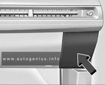
Fuse Box Location
The instrument panel fuse block is to the right of the glove box.
Universal Park Assist / Automatic Park Assist / Side Blind Zone Alert and Sensing Diagnostic Module / Automatic Occupant Sensing Module
F25
Compute Platform 2 / External Object Calculating Module / Front Camera Module / Multi Function Control and Driver Monitoring System / Central Gateway Module / Diagnostic Link Connector / Vehicle Data Monitor
F26
Electrification Control Processor Battery 2 / Air Condition Electric Compressor and Heads-Up Display / Heating, Ventilation and Air Conditioning Display
F27
Body Control Module 3
F28
Body Control Module 2
F29
Amplifier (Uplevel)
F30
Body Control Module 4
F31
Video Processing Module / SD Card / lndicator Light and Solar Sensor / Over Head Console
F32
Heated Steering Wheel Module
F33
Long Range Radar Front / Light Detection and Ranging
F34
Exterior Lighting Module 2
F35
Headlamp Left
F36
Virtual Cockpit Unit Battery 1
F37
Telematics Communication Platform (OnStar)
F38
Wireless Charger Module
F39
High Voltage System Lockout
F40
Virtual Cockpit Unit Battery 2
F41
Exterior Lighting Module 6
F42
–
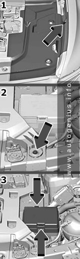
Engine Compartment Fuse Box
Fuse Box Location
The Underhood Compartment Fuse Block is under a cover and side extension/shield in the underhood compartment.