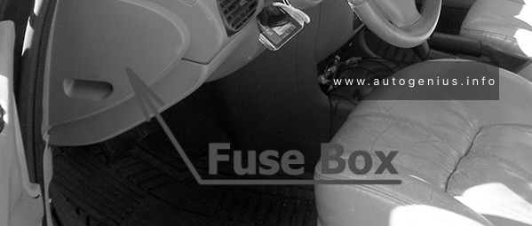
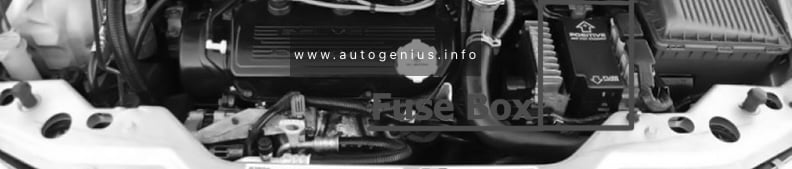
Dodge 2500 (2009 – 2011) – fuse box diagram
Year of production: 2009, 2010, 2011
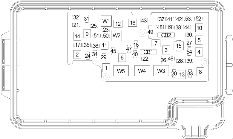
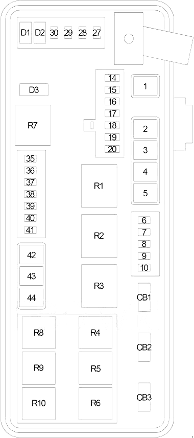
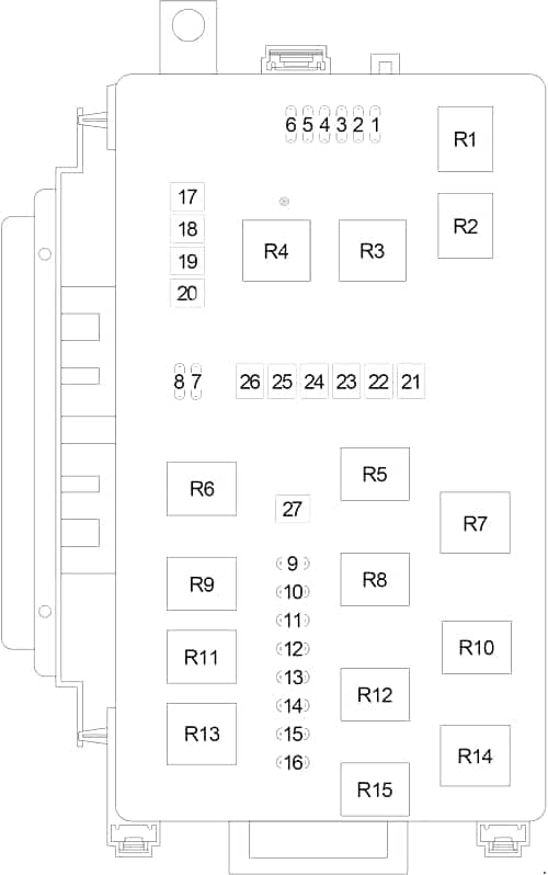
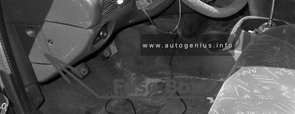
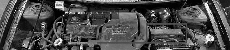
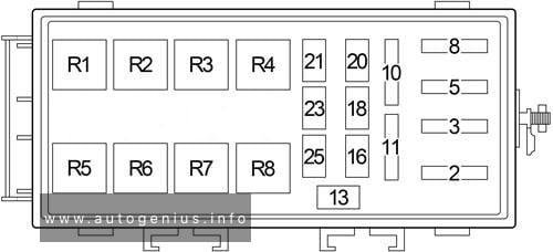
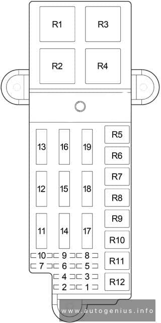
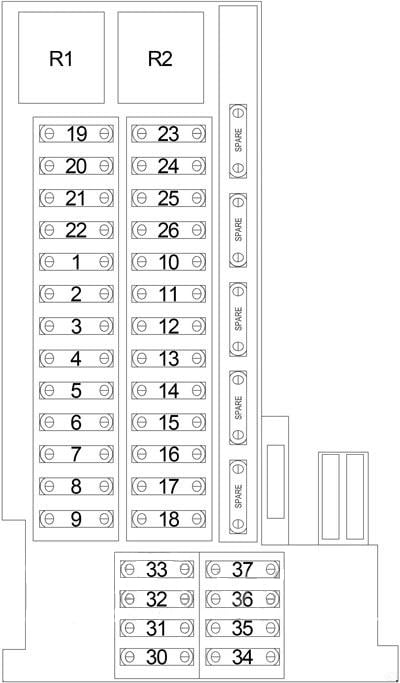
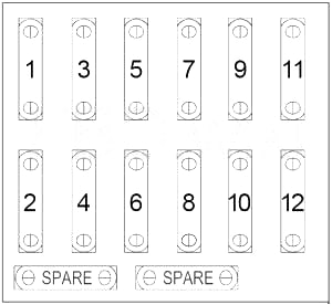
Fuse box diagram

| No. |
A |
Protected Component |
| 1 | – | – |
| 2 | 30 | Trailer Tow, Storage Left/Right Bin |
| 3 | 25 | Passenger Door Module |
| 4 | 40 | ABS |
| 5 | 30 | ABS |
| 6 | – | – |
| 7 | 25 | Driver Door Module |
| 8 | 30 | Drive Train Control Module |
| 9 | 30 | Brake Provision Module |
| 10 | – | – |
| 11 | – | – |
| 12 | 40 | Starter Relay |
| 13 | 60 | Radiator Fan (High) Relay, Radiator Fan (Low) Relay |
| 14 | – | – |
| 15 | 60 | Fuse: “38”, “39”, “41”, “42” |
| 16 | – | – |
| 17 | 25 | Sunroof Motor |
| 18 | 25 | Powertrain Control Module, Transmission Solenoid/TRS Assembly, Line Pressure Sensor/Variable Force Solenoid Assembly, Transmission Solenoid/Pressure Switch Assembly, Transmission Range Sensor |
| 19 | 5 | Window/Door Lock Switch – Passenger Side, Sunroof Motor |
| 20 | 25 | Front Wiper On/Off Relay |
| 21 | 25 | Wiper High Speed |
| 22 | 20 | Wiper Park |
| 23 | – | – |
| 24 | – | – |
| 25 | 10 | Data Link Connector, Window/Door Lock Switch – Driver Side |
| 26 | 10 | Wireless Ignition Node |
| 27 | 15 | Stop Lamp Switch, Brake Lamp Activation Relay |
| 28 | – | |
| 29 | – | |
| 30 | 25 | Inverter Module |
| 31 | 20 | Power Outlet – Instrument Panel, Power Outlet – Console |
| 32 | 20 | Washer Windshield Pump |
| 33 | 15 | Powertrain Control Module |
| 34 | 15 | Steering Control Module, Cluster, Upper Switch Bank, Lower Switch Bank |
| 35 | 20 | Heated Seats Module, |
| 36 | 20 | Heated Seats Module, Heated Rear Seats Switch |
| 37 | 10 | Horn |
| 38 | 20 | Cluster, Multi-Function Switch |
| 39 | 30 | Radio, Amplifier |
| 40 | – | – |
| 41 | 15 | Hands-Free Module, Compass Module, Video Screen Module, Satellite Video Module |
| 42 | 10 | Heating and Air Conditioning Control, Underhood Lamp |
| 43 | 10 | Horn |
| 44 | 10 | Occupant Restraint Controller Module |
| 45 | 10 | Occupant Restraint Controller Module |
| 46 | – | – |
| 47 | 10 | Heating and Air Conditioning Control, Infrared Sensor, Park Assist Module |
| 48 | 20 | Cigar Lighter, Cigar Lighter – Center Console |
| 49 | 20 | Power Outlet – Rear |
| 50 | 25 | Powertrain Control Module, Ignition Coils, Ignition Capacitor, Fuel Injector, |
| 51 | 20 | 3.7L.: Short Runner Valve Solenoid |
| 52 | 10 | Drive Train Control Module, Front Axle Disconnect Module |
| 53 | 15 | Multifunction Switch, Steering Control Module, Inside Rearview Mirror, Cluster, Transfer Case Selector Switch |
| 54 | – | – |
| CB1 | 25 | Driver/Passenger Seat Switch, Seat Memory Module, Driver/Passenger Seat Lumbar Adjuster Switch |
| CB2 | 25 | Window/Door Lock Switch – Driver Side, Power Sliding Backlite Switch, Fuse: “19” |
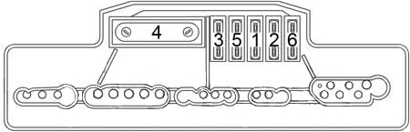
| Relay | ||
| W1 | ||
| W2 | ||
| W3 | ||
| W4 | ||
| W5 | ||
WARNING: Terminal and harness assignments for individual connectors will vary depending on vehicle equipment level, model, and market.