The pre-facelift MG ZS, a subcompact crossover, was produced from 2017 to 2020. This article includes fuse box diagrams for the 2017 through 2020 models, provides details on the locations of the fuse panels inside the vehicle, and explains the function of each fuse (fuse layout).
Fuse Box Location
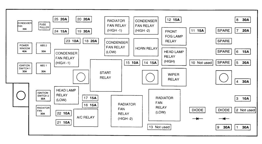
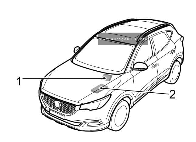
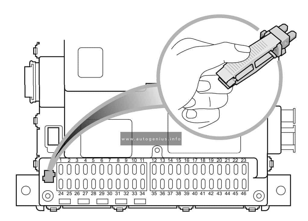
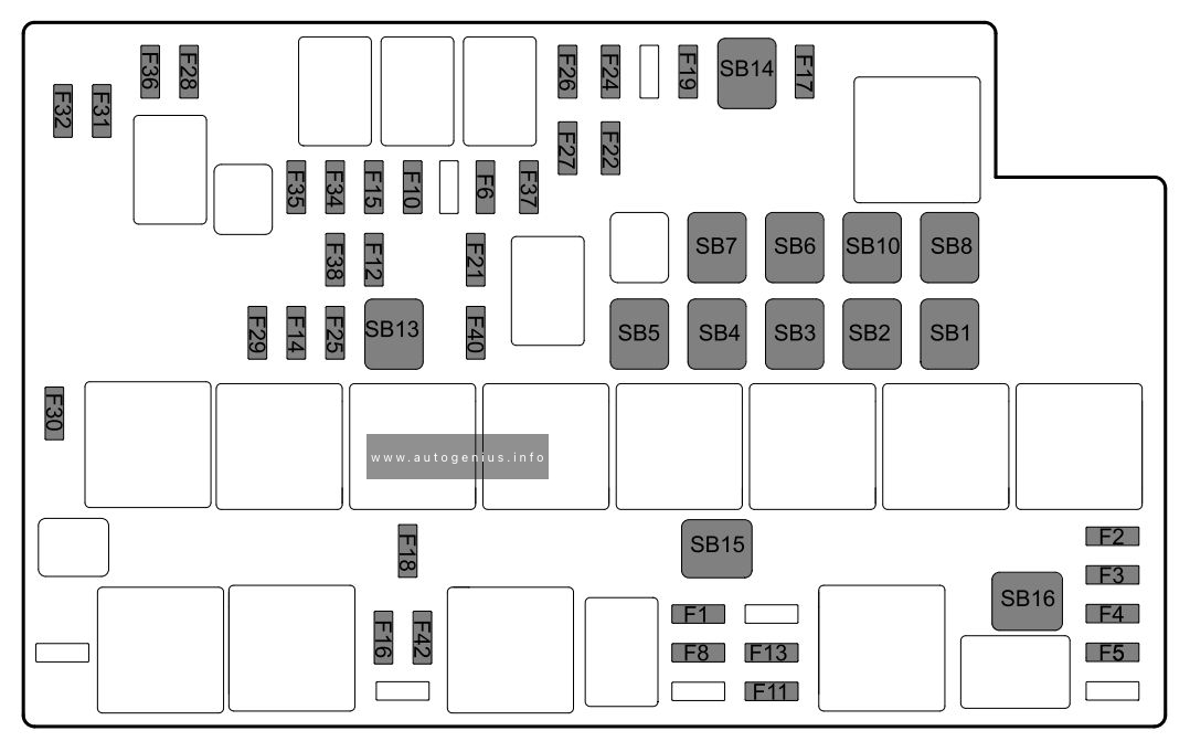
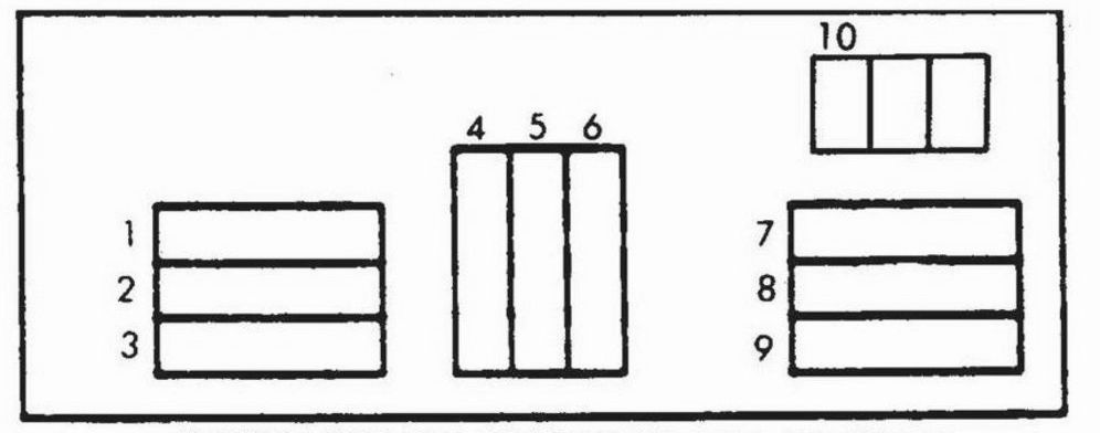
MG ZS (2017 – 2020) – fuse and relay box location
Passenger Compartment Fuse Box(below the glove box at the front passenger side
Engine Compartment Fuse Box(at the left side of the Engine Compartment
This article focuses on the facelifted first-generation MG MG6, produced from 2014 to 2016. It includes fuse box diagrams for the 2014, 2015, and 2016 models, provides information on the locations of the fuse panels inside the vehicle, and outlines the function of each fuse (fuse layout).
The MG GS, a compact crossover, was manufactured from 2015 to 2019. This article includes fuse box diagrams for the 2015 through 2019 models, provides information on the locations of the fuse panels inside the vehicle, and details the function of each fuse (fuse layout).
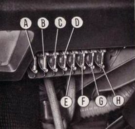
Oil pressure gage and relevant insufficient pressure indicator, Engine water temperature gage, Fuel gage and reserve indicator, Turn signal lights and indicator, Back-up lights, Heater fan motor, Windshield wiper motor, Battery charge indicator, Exhaust emission control electrovalve, Fasten belts indicator and buzzer
B
16
Courtesy lights under dash, Horns and relevant relay switch, Cigarette lighter, Vehicular hazard warning signal circuitry
C
8
Left headlight high beam
D
8
Right headlight high beam
E
8
Left headlight low beam
F
8
Right headlight low beam
G
8
Front right parking and side marker lights, Rear left tail and side marker lights, License plate light (right), (Instrument cluster lights, Cigarette lighter housing indicator
WARNING: Terminal and harness assignments for individual connectors will vary depending on vehicle equipment level, model, and market.
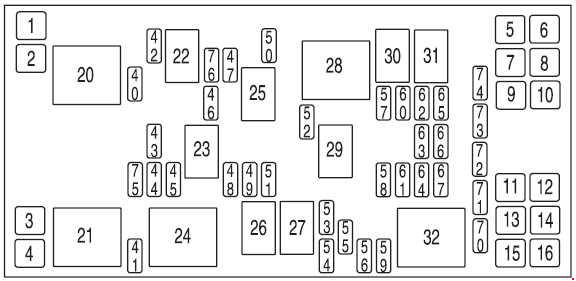
SJB #1 – Center High-Mounted Stop Lamp (CHMSL), License plate lamps, OBD II, Dome lamp, Auxiliary blend doors, Switch illumination (feeds F-8, F-9, F-10nd F-ll)
59
20
Radio (non-premium)
60
30
SJB #4 – Back-up lamps, Theft sounder (’04), Door locks
61
20
’04: 3rd row power point
62
30
SJB #3 – Right comering/auxiliary lamps, Right low beam, Left front park/turn lamps, Left rear park/stop/tum lamps, Instrument panel courtesy lamps, Step well lamps, Left signal mirror, Clock, Cluster, Message center (SJB F-15), Switch illumination for: overhead console, DVD/Rear climate control system, Headlamp switch illumination, Climate control illumination
63
20
Instrument panel power point, Cigar lighter (’05-’07)
64
20
Ignition switch #1 feed
65
30
SJB #2 – Left cornering/auxiliary lamps, Left low beam, Right front park/turn lamps, Right rear park/stop/turn lamps, Puddle lamps, Mirror signals, Visors, 2nd and 3rd row lamps, Cargo lamp, Defroster indicator
66
20
2nd row seat power point, 3rd row power point (’05-’07)
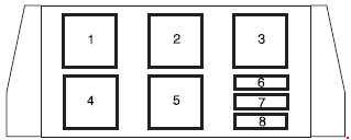
Radiator Fan Relay, Radiator Fan Motor, Air Conditioner System, Daytime Light Control Unit, Theft Warning Relay
3
20
Stoplight Switch, Cruise Control, Unit, A/T Control Unit, Shift Lock Control Unit, Anit-Lock Brake System Control Unit, Power Steering Control Unit, Radiator Fan Motor, HICAS Control Unit
4
10
Shift Lock Control Control Unit, Key Switch
5
15
Front Foglights, Headlight Washer Motor
6
20
Ani-Lock Brake System
7
10
Horn, Time Control Unit, Cruise Control
8
15
Right Headlight, Daytime Light Control Unit
9
15
Left Headlight, Daytime Light Control Unit
10
10
A/T Control Unit, Theft Warning Control Unit, auto A/C Control Amp., Key Hole Illumination, Footlights, audio, HICAS Control Unit, Clock, Air Bag Control Unit
WARNING: Terminal and harness assignments for individual connectors will vary depending on vehicle equipment level, model, and market.