Acura CL (YA4; 2003) – fuse and relay box diagram
Year of production: 2003
This article covers the second-generation Acura CL, produced from 1997 to 2003. It includes fuse box diagrams for the 2003 models, provides details on the location of the fuse panels inside the vehicle, and explains the function and layout of each fuse.
Engine compartment
Fuse box diagram

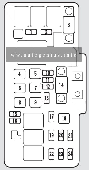
Assignment of the fuses in the engine compartment
| Fuse | Ampere rating [A] | Circuits Protected |
| 1*1 | 20 | Condenser Fan |
| 1*2 | 30 | Condenser Fan |
| 2 | 7,5 | MG Clutch |
| 3 | 60 | IG1 Main |
| 4 | 40 | Rear Window Defogger |
| 5 | 40 | Heater Motor |
| 6*1 | 20 | TCS |
| 6*2 | 40 | VSA |
| 6*3 | — | Not used |
| 7 | 40 | Power Seat |
| 8 | 40 | Power Window Motor |
| 9 | 40 | Back Up, ACC |
| 10 | 15 | Spare Fuse |
| 11 | 10 | Spare Fuse |
| 12 | 7,5 | Spare Fuse |
| 13*1,*3 | 20 | Cooling Fan |
| 13*2 | 30 | Cooling Fan |
| 14 | 120 | Battery |
| 15 | 30 | Spare Fuse |
| 16 | 20 | Spare Fuse |
| 17 | 15 | Hazard |
| 18 | 30 | ABS Motor |
| 19 | 15 | ACG S |
| 20 | 20 | Stop |
| 21 | 20 | ABS F/S Relay |
| 22 | 20 | Right Headlight |
| 23 | — | Not used |
| 24 | 20 | Left Headlight |
*1 – Premium model
*2 – Type-S with A/T
*3 – Type-S with M/T
Passenger compartment
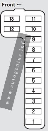
Fuse box diagram (driver’s side)

Assignment of the fuses in the passenger compartment (driver’s side)
| Fuse | Ampere rating [A] | Circuits Protected |
| 1 | 15 | Fuel Pump |
| 2 | 10 | Main SRS |
| 3 | 7,5 | Heater Control, A/C Clutch Relay, Cooling Fan Relay |
| 4 | 7,5 | Mirror, Heated Seat, Heated Mirror |
| 5 | 7,5 | Daytime Running Lights* |
| 6 | 15 | ECU (PCM), Cruise Control, VSA |
| 7 | 7,5 | Side SRS |
| 8 | 7,5 | ACC Relay, Navigation |
| 9 | 7,5 | Instrument Panel, Back-up Lights, Memory Seat |
| 10 | 7,5 | Turn Signals |
| 11 | 15 | IG Coil |
| 12 | 30 | Wiper, Washer |
| 13 | 7,5 | Starter Signal |
*-On Canadian models
Fuse box diagram (passenger’s side)
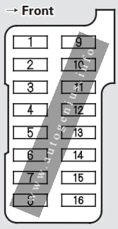
Assignment of the fuses in the passenger compartment (passenger’s side)
| Fuse | Ampere rating [A] | Circuits protected |
| 1 | 30 | Left Power Window |
| 2 | 20 | Driver’s Power Seat Reclining, Memory Seat |
| 3 | 20 | Heated Seat |
| 4 | 20 | Driver’s Power Seat Sliding, Memory Seat |
| 5 | 20 | Passenger’s Power Seat Sliding |
| 6 | 20 | Passenger’s Power Seat Reclining |
| 7 | 30 | Moonroof Motor |
| 8 | 20 | Right Power Window |
| 9 | 20 | Radio, Power Outlet |
| 10 | 10 | Navigation System, Daytime Running Lights*1, OnStar*2 |
| 11 | 7,5 | Interior Light, Seat Memory, HomeLink |
| 12 | 20 | Power Door Locks |
| 13 | 15 | Clock, Back Up, Small Light |
| 14 | 7,5 | ABS Motor Check |
| 15 | — | Not used |
| 16 | — | Not used |
*1 – On Canadian models
*2 – On cars with navigation system
VSA fuse box (on type S with A/T)
Fuse box location
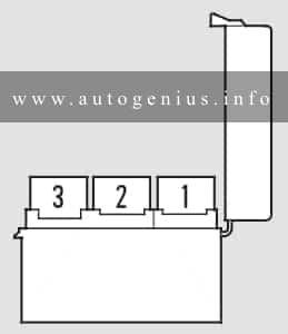
The VSA fuse box is located under the interior fuse box on the passenger’s side of the dashboard.
Fuse box diagram

Assignment of the fuses in the VSA fuse box
| Fuse | Ampere rating [A] | Circuits protected |
| 1 | 20 | VSA F/S Relay |
| 2 | 20 | VSA Throttle Motor |
| 3 | — | Not Used |
WARNING: Terminal and harness assignments for individual connectors will vary depending on vehicle equipment level, model, and market.