Mercedes-Benz S-Class (w222) (2014 – 2018) – fuse box diagram
Year of production: 2014, 2015, 2016, 2017, 2018
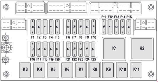
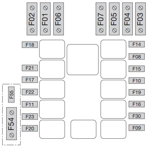
Fuse and relay box in engine compartment
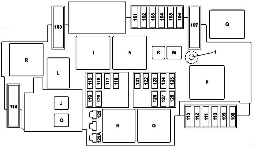
| Number | Fused function | Ampers |
| 100 | Hybrid: Vacuum pump | 40 |
| 101 | Connector sleeve, circuit 87/2 | 15 |
| 102 | Connector sleeve, circuit 87/2 | 20 |
| 103 | Connector sleeve, circuit 87M4 | 15 |
| 104 | Connector sleeve, circuit 87M3 | 15 |
| 105 | Valid for transmission 722.9: Transmission oil auxiliary pump control unit | 15 |
| 106 | Wiper park position heater | 25 |
| 107 | Valid for engine 277, 279: Starter/air pump electrical connection | 60 |
| 108 | Valid for SAE dynamic LED headlamp for right-hand traffic or Dynamic LED headlamp:: Left front lamp unit Right front lamp unit Valid without SAE dynamic LED headlamp for right-hand traffic or Dynamic LED headlamp:: Right front lamp unit |
20 |
| 109 | Wiper motor | 30 |
| 110 | Valid for code SAE dynamic LED headlamp for right-hand traffic or Dynamic LED headlamp:: Left front lamp unit Right front lamp unit Valid without SAE dynamic LED headlamp for right-hand traffic or Dynamic LED headlamp:: Left front lamp unit |
20 |
| 111 | Starter | 30 |
| 112 | Engine fuse and relay module | 5 |
| 113 | Spare | — |
| 114 | AIRmatic compressor | 40 |
| 115 | Left fanfare horn Right fanfare horn |
15 |
| 116 | Hybrid: Vacuum pump relay | 5 |
| 117 | Spare | — |
| 118 | Hybrid: Electronic Stability Program control unit | 5 |
| 119 | Circuit 87/C2 connector sleeve | 15 |
| 120 | Circuit 87/C1 connector sleeve | 7,5 |
| 121 | Electronic Stability Program control unit | 5 |
| 122 | Hybrid: HYBRID relay | 5 |
| 123 | Night View Assist control unit | 5 |
| 124 | Hybrid: Vehicle interior and engine compartment electrical connector | 5 |
| 125 | Front SAM control unit | 5 |
| 126 | Powertrain control uni Valid for diesel engine: CDI control unit Valid for gasoline engine: ME-SFI [ME] control unit |
5 |
| 127 | Spare | — |
| 128 | Exterior lights switch | 5 |
| 129A | Hybrid: Starter circuit 50 relay | 30 |
| 129B | Valid except Hybrid: Starter circuit 50 relay | 30 |
| Relay | ||
| G | Engine compartment circuit 15 relay | |
| H | Starter circuit 50 relay | |
| I | Brake vacuum pump relay | |
| J | Hybrid: HYBRID relay | |
| K | Transmission oil pump relay | |
| L | Horn relay | |
| M | Wiper park position heater relay | |
| N | Circuit 87M relay | |
| O | Valid except Hybrid: Starter circuit 15 relay | |
| P | Secondary air injection relay | |
| Q | Hybrid: Vacuum pump relay | |
| R | AIRmatic relay | |
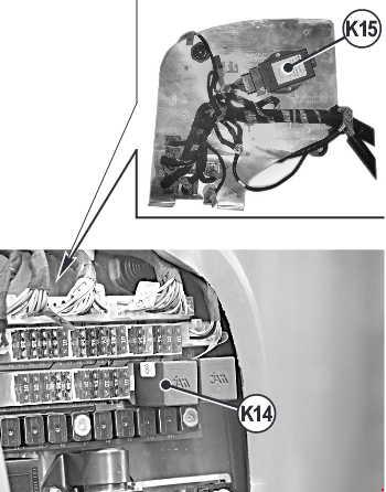
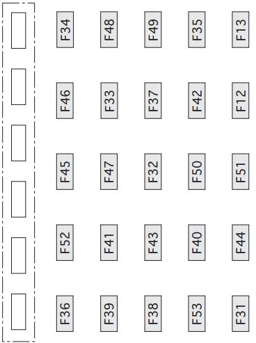
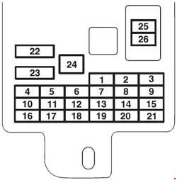
The Instrument Panel Fuse Panel
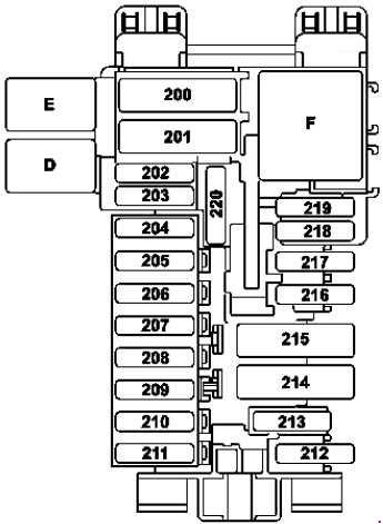
| Number | Fused function | Ampers |
| 200 | Front SAM control unit | 40 |
| 201 | Front SAM control unit | 40 |
| 202 | Alarm siren | 5 |
| 203 | W222: Driver seat heater control unit | 30 |
| 204 | Diagnostic connector | 5 |
| 205 | Electronic ignition lock control unit | 7,5 |
| 206 | Analog clock | 5 |
| 207 | Climate control control unit | 20 |
| 208 | Instrument cluster | 7,5 |
| 209 | Front climate control operating unit | 5 |
| 210 | Steering column tube module control unit | 10 |
| 211 | Spare | — |
| 212 | Spare | — |
| 213 | Electronic Stability Program control unit | 25 |
| 214 | Spare | — |
| 215 | Spare | — |
| 216 | Spare | — |
| 217 | Japanese version: Dedicated Short-Range Communications control unit | 5 |
| 218 | Supplemental restraint system control unit | 5 |
| 219 | Weight sensing system (WSS) control unit Front passenger seat occupied recognition and ACSR |
5 |
| 220 | MAGIC VISION CONTROL relay | 15 |
| Relay | ||
| D | MAGIC VISION CONTROL relay | |
| E | Backup relay | |
| F | Relay, circuit 15R | |
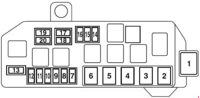
Fuse box in the front-passenger footwell
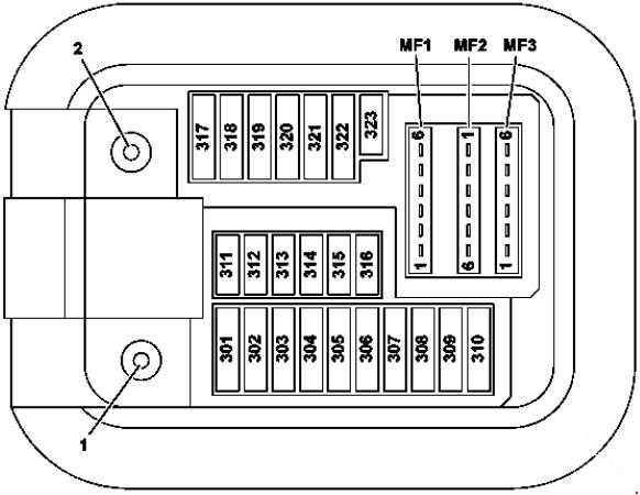
- Circuit 30 “E1” connection
- Circuit 30g “E2” connection
| Number | Fused function | Ampers |
| 301 | Mirror taximeter | 5 |
| 302 | Right front door control unit | 30 |
| 303 | W222: Left rear door control unit C217, A217: Rear control unit |
30 |
| 304 | W222: Right rear door control unit C217, A217: Rear control unit |
30 |
| 305 | Driver seat control unit | 30 |
| 306 | Front passenger seat control unit | 30 |
| 307 | W222: Intelligent servo module for DIRECT SELECT | 30 |
| C217, A217: Driver seat heater control unit | 30 | |
| 308 | Front passenger seat heater control unit | 30 |
| 309 | Emergency call system control unit Telematics services communications module HERMES control unit |
5 |
| 310 | Stationary heater control unit | 25 |
| 311 | Rear blower motor | 10 |
| 312 | Overhead control panel control unit | 10 |
| 313 | Hybrid and Hybrid Plus: Power electronics control unit | 10 |
| 314 | A217: Antitheft alarm system (designation in coordination) | 7,5 |
| 315 | Powertrain control unit Valid for gasoline engine: ME-SFI control unit Valid for engine 642, 651: CDI control unit |
10 |
| 316 | Spare | — |
| 317 | W222: Panoramic sliding sunroof control module C217, A217: MAGIC SKY CONTROL control unit |
30 |
| 318 | Audio/COMAND display | 15 |
| 319 | Panoramic sliding sunroof control module C217, A217: Panoramic roof roller sun blind control module |
30 |
| 320 | Active Body Control control unit AIRmatic control unit (Valid except Active Body Control) |
15 |
| 321 | C217, A217: Intelligent servo module for DIRECT SELECT | 20 |
| 322 | COMAND controller unit | 15 |
| 323 | Supplemental Restraint System control unit | 7,5 |
| MF1/1 | Japan version: Dedicated Short-Range Communications control unit | 7,5 |
| MF1/2 | Mono multifunction camera Stereo multifunction camera |
7,5 |
| MF1/3 | Rain/light sensor with additional functions Overhead control panel control unit |
7,5 |
| MF1/4 | Driver seat control unit | 7,5 |
| MF1/5 | Front passenger seat control unit | 7,5 |
| MF1/6 | Steering column tube module control unit | 7,5 |
| MF2/1 | Perfume atomizer generator | 5 |
| MF2/2 | Audio/COMAND control panel Touchpad |
5 |
| MF2/3 | Electronic Stability Program control unit | 5 |
| MF2/4 | Heads-up display | 5 |
| MF2/5 | Hybrid and Hybrid Plus: Electrical refrigerant compressor | 5 |
| MF2/6 | Spare | — |
| MF3/1 | Front SAM control unit | 5 |
| MF3/2 | Radar sensors control unit | 5 |
| MF3/3 | COMAND fan motor | 5 |
| MF3/4 | Driver side instrument panel button group Center instrument panel button group |
5 |
| MF3/5 | Rear air conditioning operating unit | 5 |
| MF3/6 | as of 01.06.2016: Antenna changeover switch for telephone and stationary heater | 5 |
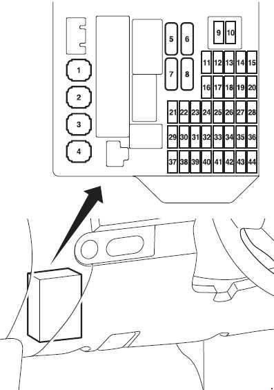
Fuse and relay box in rear

- Circuit 30 “E1” connection
- Circuit 30g “E2” connection
| Number | Fused function | Ampers |
| 400 | Parking system control unit (Active Parking Assist or code 360-degree camera) | 10 |
| 401 | Trunk lid control control unit | 5 |
| 402 | Rear entertainment controller unit | 7,5 |
| 403 | Spare | — |
| 404 | Armrest heater control unit | 7,5 |
| 405 | Sound system amplifier control unit Left front door tweeter control unit Right front door tweeter control unit |
7,5 |
| 406 | Spare | — |
| 407 | Spare | — |
| 408 | Tuner unit | 5 |
| 409 | 360° camera control unit Reversing camera |
5 |
| 410 | Camera cover control unit | 5 |
| 411 | Tire pressure monitor control unit | 5 |
| 412 | Rear seat heater control unit | 7,5 |
| 413 | Left rear display Right rear display |
10 |
| 414 | Rear cellular telephone system antenna amplifier/compensator Rear mobile phone cradle Rear mobile phone contact plate Telephone module with Bluetooth® (SAP profile) |
7,5 |
| 415 | Spare | — |
| 416 | Spare | — |
| 417 | Trailer recognition control unit | 20 |
| 418 | Spare | — |
| 419 | Spare | — |
| 420 | DC/AC converter control unit | 30 |
| 421 | Multicontour seat pneumatic pump | 30 |
| 422 | W222: Right rear door control unit | 30 |
| 423 | Spare | — |
| 424 | Rear SAM control unit | 40 |
| 425 | Spare | — |
| 426 | Bass speaker amplifier | 30 |
| 427 | Armrest heater control unit | 20 |
| 428 | Trailer recognition control unit | 15 |
| 429 | Rear cup holder | 10 |
| 430 | Cigarette lighter with ashtray illumination, rear Cigarette lighter with rear center console illumination Left rear center console socket 12V (ashtray package/smoker package) |
15 |
| 431 | Rear backrest refrigerator box | 15 |
| 432 | Rear SAM control unit | 10 |
| 433 | AdBlue® control unit | 25 |
| 434 | AdBlue® control unit | 15 |
| 435 | AdBlue® control unit | 20 |
| 436 | Rear cup holder | 20 |
| 437 | Spare | — |
| 438 | C217 with engine 157: Right exhaust flap actuator motor | 7,5 |
| 439 | C217 with engine 157: Left exhaust flap actuator motor | 7,5 |
| 440 | Spare | — |
| 441 | Spare | — |
| 442 | Spare | — |
| 443 | Spare | — |
| 444 | Spare | — |
| 445 | Stationary heater radio remote control receiver | 5 |
| 446 | FM 1, AM, CL [ZV] and KEYLESS-GO antenna amplifier | 5 |
| 447 | Hybrid: Battery management system control unit | 7,5 |
| 448 | Spare | — |
| 449 | Spare | — |
| 450 | Spare | — |
| 451 | Trailer socket | 15 |
| 452 | Left rear bumper radar sensor Right rear bumper radar sensor Center rear bumper radar sensor |
5 |
| 453 | Left front bumper radar sensor Right front bumper radar sensor COLLISION PREVENTION ASSIST controller unit |
5 |
| 454 | AdBlue® control unit Fuel system control unit |
5 |
| 455 | Fully integrated transmission control controller unit | 15 |
| 456 | Spare | — |
| 457 | Valid for lithium-ion battery: Starter battery capacitor | 7,5 |
| 458 | Spare | — |
| 459 | Spare | — |
| 460 | Front cigarette lighter with ashtray illumination | 15 |
| 461 | Right rear center console socket 12V Socket 12V DC/AC converter control unit |
15 |
| 462 | Luggage compartment socket | 15 |
| 463 | Spare | — |
| 464 | Trailer recognition control unit | 20 |
| 465 | Electric parking brake control unit | 30 |
| 466 | Left front door control unit | 30 |
| 467 | KEYLESS-GO control unit | 10 |
| 468 | Electric parking brake control unit | 30 |
| 469 | Fuel system control unit | 25 |
| 470 | Left rear seat heater control unit Rear seat heater control unit |
30 |
| 471 | Right rear seat heater control unit | 30 |
| 472 | C217, A217: Rear control unit | 30 |
| 473 | Trailer recognition control unit | 20 |
| 475 | Sound system amplifier control unit | 40 |
| 476 | Sound system amplifier control unit | 40 |
| 477 | Active belt buckle control unit C217, A217: Rear control unit |
40 |
| 478 | Left rear seat control unit | 30 |
| 479 | Active belt buckle control unit | 40 |
| 480 | Right rear seat control unit | 30 |
| 481 | Left front reversible emergency tensioning retractor | 5 |
| 482 | W222: MAGIC SKY CONTROL control unit | 5 |
| C217, A217: MAGIC SKY CONTROL control unit | 7,5 | |
| 483 | Right front reversible emergency tensioning retractor | 5 |
| 484 | Right rear seat control unit Left rear seat control unit |
7,5 |
| 485 | Active belt buckle control unit | 5 |
| 486 | Hybrid: Battery management system control unit Power electronics control unit |
10 |
| 487 | Electric parking brake control unit | 5 |
| 488 | Rear SAM control unit | 5 |
| 489 | Front long-range radar sensor | 5 |
| 490 | Multicontour seat pneumatic pump | 5 |
| 491 | Trunk lid control control unit | 40 |
| 492 | Right front reversible emergency tensioning retractor | 40 |
| 493 | Spare | — |
| 494 | Rear SAM control unit | 40 |
| 495 | Rear window heater | 40 |
| 496 | Left front reversible emergency tensioning retractor | 40 |
| Relay | ||
| S | Vehicle interior circuit 15 relay | |
| T | Rear window heater relay | |
| U | 2nd seat row cupholder and sockets relay | |
| V | AdBlue® relay | |
| W | Circuit 15R relay | |
| X | 1 st seat row/trunk refrigerator box and sockets relay | |
| Y | Spare relay | |
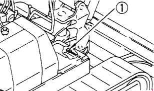
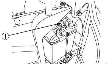
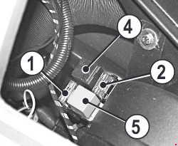
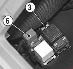
Engine compartment prefuse box
View from below
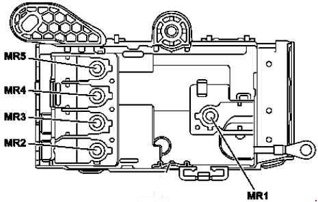
View from above
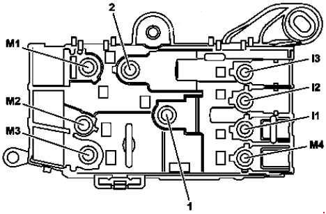
1 – Connection, circuit 30 “B1”
2 – Connection, circuit 30 unlatched “B2”
| Number | Fused function | Ampers |
| M3 | Hybrid: Electrical machine | 500 |
| Valid except Hybrid: Alternator | 500 | |
| M1 | Hybrid: Electrical machine | — |
| Valid except Hybrid: Starter | — | |
| MR5 | Electrical power steering control unit | 100 |
| MR2 | Fan motor | 100 |
| M4 | Hybrid: Fully integrated transmission control controller unit | 100 |
| I1 | Spare | — |
| M2 | Valid for diesel engine: Glow output stage | 150 |
| MR1 | Motor fuse and relay module | 60 |
| MR3 | Spare | — |
| MR4 | Valid for engine 277, 279: Fan motor | 150 |
| I2 | Spare | — |
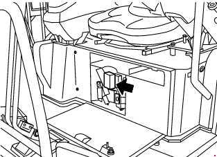
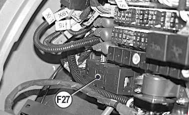
Vehicle interior prefuse box
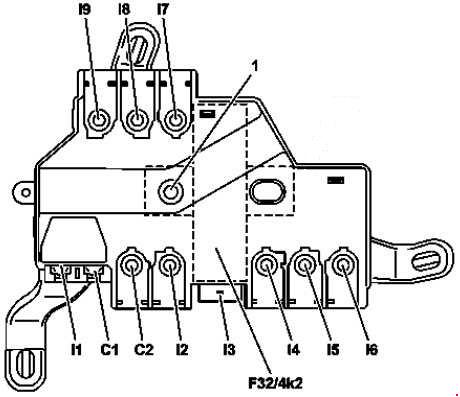
F32/4k2 – Quiescent current cutout relay
| Number | Fused function | Ampers |
| I7 | Right A-pillar fuse box | 125 |
| I2 | Left fuse and relay module | 125 |
| C2 | Spare | — |
| I8 | Spare | — |
| I9 | Spare | — |
| I3 | No-load current shutoff relay connection | — |
| C1 | Blower regulator | 40 |
| I1 | Electronic Stability Program control unit | 40 |
| I4 | Spare | — |
| I6 | Rear fuse and relay module | 60 |
| I5 | Right A-pillar fuse box | 60 |
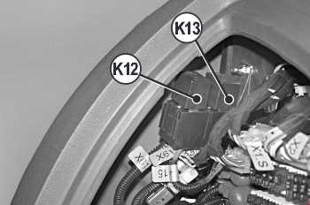
Rear prefuse box
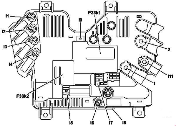
F33k1 – Decoupling relay
F33k2 – ECO start/stop function additional battery relay
| Number | Fused function | Ampers |
| I3 | Spare | — |
| I2 | Windshield heater control unit | 125 |
| I7 | Hybrid: High-voltage disconnect device | 7,5 |
| I4 | Rear fuse and relay module | 150 |
| I6 | ECO start/stop function additional battery | 200 |
| I7 | ECO start/stop function additional battery Front SAM control unit Electronic ignition lock control unit |
10 |
| I1 | Spare | — |
| I11 | Spare | — |
| I7 | Front SAM control unit | 10 |
| I8 | ECO start/stop function additional battery relay connection | — |
| I5 | Hybrid: High-voltage pyrofuse triggered by Supplemental Restraint System control unit | — |
| I9 | Decoupling relay connection | — |
WARNING: Terminal and harness assignments for individual connectors will vary depending on vehicle equipment level, model, and market.