| Numer |
Amprere ratting [A] |
Function |
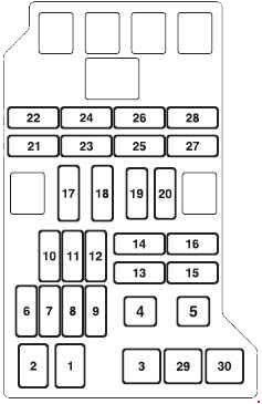
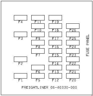
| F1 |
5 |
1999-2001: Starter relay coil via Park/Neutral switch
2002-2008: Engine control module/crankshaft sensor |
| F2 |
5 |
1999-2001: Radio |
| F3 |
5 |
ABS/Dynamic stability control module, ACC module (2002-2008) |
| F4 |
5 |
Inertia switch (fuel pump relay, ignition control relay, rear electronics module), instrument cluster, brake pedal cruise de-activation switch (2002-2003), bottom of clutch switch (2003), engine management system (2006-2008), cruise control cancel (2006-2008)
Powertrain Control Module (PCM) relay coil (1999-2001), transit relay (1999-2001) |
| F5 |
10 |
2002-2008: Restraint control module, airbag occupant sensor, passenger airbag de-activation lamp |
| 5 |
1999-2001: Autolamp sensor, traction control switch, overdrive cancel switch, heated seat modules, brake shift interlock |
| F6 |
10 |
OBDII connector |
| F7 |
5 |
1999-2001: Driver’s Door Module (DDM), Driver’s Seat Module (DSM), Powertrain Control Module (PCM), Passive Anti-Theft System (PATS) LED, security horn, power mirror
2002-2008: Driver’s door module, seat logic (2002-2003), battery backed sounder, road pricing (Singapore), security LED |
| F8 |
5 |
Front right turn indicator, sidemarker, park, repeater lamps |
| F9 |
10 |
Right-hand dipped beam, left-hand HID relay coil |
| F10 |
5 |
Front left turn indicator, sidemarker, park, repeater lamps |
| F11 |
10 |
Left-hand main beam |
| F12 |
15 |
2002-2008: Screenwash pump |
| 10 |
1999-2001: Headlamp levelling |
| F13 |
5 |
Instrument cluster |
| F14 |
10 |
1999-2001: Restraints Control Module (Airbag), Dual Automatic Temperature Control Module
2002-2008: Climate control system, two stage adaptive damping control module |
| F15 |
5 |
1999-2001: Adaptive damping module (CATS)
2002-2008: Ignition switch feed (RUN) to alternator, T-gate, transmission control module |
| F16 |
10 |
2002-2008: Passenger/driver heated seat modules, electrochromic mirror, rain sense module, headlamp levelling, ACC chime module (2002-2003), tyre pressure module (2004-2007) |
| 5 |
1999-2001: Heated seat switch module, electrochromic mirror, rain sensor |
| F17 |
5 |
1999-2001: Restraints Control Module (Airbag), alternator warning lamp
2002-2008: Instrument cluster (airbag warning light, alternator warning light, seatbelt chime) |
| F18 |
20 |
1999-2001: Radio, cellular phone, navigation
2002-2008: Radio head unit, touchscreen/display unit |
| F19 |
15 |
Steering column tilt and reach motors |
| F20 |
10 |
1999-2001: Generic Electronic Module (GEM), air conditioning, instrument cluster, rear electronic control module
2002-2008: Logic supply to instrument cluster, climate control system, front electronic module, rear electronic module, electric parkbrake (2004-2008) |
| F21 |
10 |
1999-2001: Power folding mirror, sunblind |
| F22 |
10 |
Driver’s door module battery supply (driver’s door mirror, locks) |
| F23 |
10 |
Right-hand main beam |
| F24 |
5 |
Passive anti-theft system |
| F25 |
10 |
Left-hand dipped beam, right-hand HID relay coil |
| F26 |
10 |
2002-2008: Electric parkbrake switch illumination, AM/FM antenna amplifier, sunblind motor, accessory socket relay (cigar lighter and power point relay) |
| F27 |
10 |
1999-2001: Navigation display, radio, phone, navigation module, traffic master
2002-2008: Radio head unit, touchscreen/display unit, navigation module, voice control, VICS (Japan), centre console switchpack, phone transceiver (2004-2008) |
| F28 |
5 |
1999-2001: Security horn |
| F29 |
5 |
1999-2001: Voice control, reverse park aid, trailer tow ignition sense, Vehicle Emergency Messaging System (VEMS), Generic Electronic Module (GEM)
2002-2008: Voice control, reversing aid module, telephone transceiver, front electronic module |
| F30 |
10 |
2002-2008: Front electronic module power |
| 5 |
1999-2001: Generic Electronic Module (GEM), passenger power mirror |
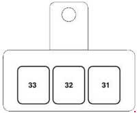
| F31 |
— |
— |
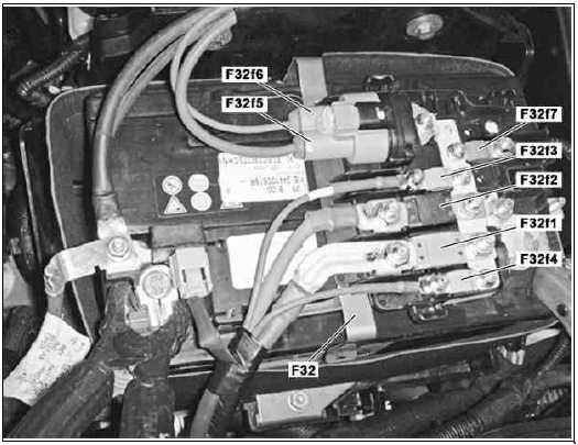
| F32 |
20 |
Accessory relay (cigar lighter, power point) |
| F33 |
10 |
1999-2001: Generic Electronic Module (GEM)
2002-2008: Front electronic module (instrument dimming, fuel/luggage compartment switchpack |
| F34 |
— |
— |
| F35 |
5 |
1999-2001: Stop lamp switch
2002-2008: Brake on/off switch, cruise control cancel switch (2002-2003), bottom of clutch switch (2002, 2004-2008) |
| Relay |
| R1 |
40 |
Accessory (cigar lighter, power point) |