| Number |
Ampere rating [A] |
Description |
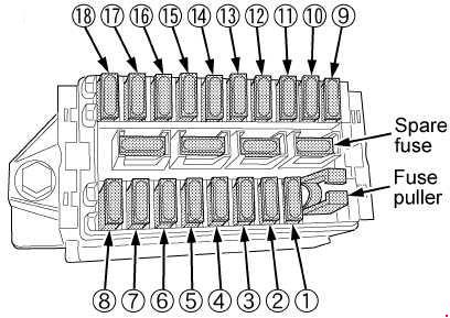
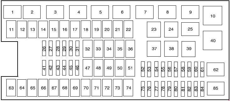
| 11 |
30 |
Power running board motors |
| 12 |
40 |
2010-2014: Electric fan |
| 50 |
2011-2014: Electric fan (3.5L, 6.2L with max trailer tow, SVT Raptor) |
| 13 |
30 |
Starter relay power |
| 14 |
30 |
Passenger power seat |
| 15 |
40 |
2010-2014: Electric fan |
| 50 |
2011-2014: Electric fan (3.5L, 6.2L wlth max trailer tow, SVT Raptor) |
| 16 |
20 |
2013-2014: Hlgh-lntenslty discharge headlamp -passenger side |
| 17 |
30 |
Trailer brake control |
| 18 |
30 |
2010-2014: Auxiliary switch 1 (SVT Raptor) |
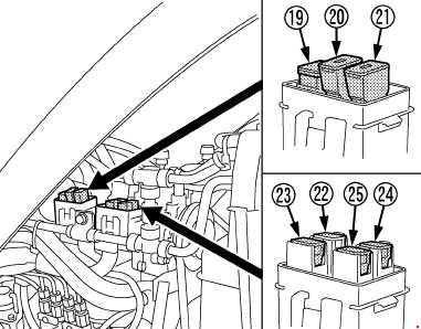
| 19 |
30 |
2010-2014: Auxiliary switch 2 (SVT Raptor) |
| 20 |
20 |
4×4 module (electronic shift) |
| 21 |
30 |
Trailer tow battery charge relay power |
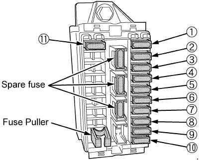
| 22 |
30 |
Auxiliary power point (Instrument panel) |
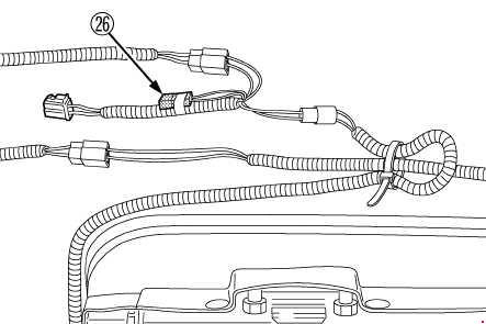
| 26 |
10 |
Powertrain control module – keep alive power and relay coll, canister vent solenoid, transmission (2009-2010) |
| 27 |
20 |
Fuel pump relay power |
| 28 |
10 |
2010-2014: Auxiliary switch 4 (SVT Raptor) |
| 29 |
10 |
4×4 integrated wheel end solenoid |
| 30 |
10 |
Air conditioner clutch relay power |
| 31 |
15 |
2011-2014: Run/start relay power |
| 20 |
2009-2010: Trailer tow park lamp relay |
| 32 |
40 |
Rear window defroster relay power, Heated mirror relay power |
| 33 |
40 |
2011-2014: 110-volt AC power point |
| 34 |
40 |
2009-2014: Powertrain control module relay power |
| 50 |
2011-2014: Powertrain control module relay power (3.5L engine) |
| 35 |
20 |
2013-2014: Hlgh-lntenslty discharge headlamps -driver side |
| 36 |
30 |
Roll stability control / Anti-lock brake system |
| 41 |
15 |
2012-2014: Front camera washer (SVT Raptor)
2010: Heated mirror |
| 42 |
5 |
2011-2014: Run/start relay coll |
| 43 |
15 |
2011-2014: Trailer tow back-up lamp relay power |
| 20 |
2009-2010: Backup lamp relay |
| 44 |
15 |
2010-2014: Auxiliary switch 3 (SVT Raptor), Trailer tow power folding mirrors |
| 45 |
10 |
2011-2014: Alternator sensor |
| 20 |
2009-2010: Trailer tow stop turn relay feed |
| 46 |
10 |
Brake on/off switch |
| 47 |
60 |
Roll stability control / Anti-lock brake system module (2011-2014) |
| 48 |
20 |
2011-2014: Moonroof |
| 49 |
30 |
Wiper relay power |
| 50 |
— |
— |
| 51 |
40 |
Blower motor relay power |
| 52 |
5 |
2011-2014: Run/start – Electronic power assist steering. Blower relay coll |
| 53 |
5 |
2011-2014: Run/start – Powertrain control module
2009-2010: PCM, 6R80 transmission |
| 54 |
5 |
2011-2014: Run/start – 4×4 module. Back-up lamps, Roll stability control /Anti-lock brake system. Trailer tow battery charge relay coll. Rear window defroster relay coll. Front camera washer relay coll (SVT Raptor)
2009-2010: 4×4 module, Back up lamp, RSC, Trailer tow battery charge relay |
| 55 |
5 |
2009-2010: Electronic compass mirror (6R transmission only) |
| 56 |
15 |
2011-2014: Heated mirrors |
| 57 |
— |
— |
| 58 |
15 |
2009-2010:Trailer tow backup lamps |
| 59 |
15 |
2009: Heated mirrors |
| 60 |
— |
2009-2010: One-touch Start diode |
| 61 |
— |
2009-2010: Fuel pump diode |
| 63 |
25 |
2010-2014: Electric fan relay power |
| 64 |
30 |
2009-2010: Amplifier |
| 40 |
2011-2012: Vacuum pump relay power (3.5L engine) |
| 65 |
20 |
Auxiliary power point (Instrument panel) |
| 66 |
20 |
Auxiliary power point (Inside center console) |
| 67 |
20 |
2011-2014: Trailer tow park lamps relay power |
| 68 |
25 |
4×4 module, 4×2 elocker module (2013-2014) |
| 69 |
30 |
Front heated or heated/cooled seats |
| 70 |
— |
— |
| 71 |
20 |
2011-2014: Heated rear seats |
| 72 |
20 |
Auxiliary power point (rear) |
| 73 |
20 |
2011-2014: Trailer tow stop/turn lamps relay power |
| 74 |
30 |
Driver power seat/memory module |
| 75 |
15 |
2009-2014: Powertrain control module – voltage power 1 |
| 25 |
2011-2014: Powertrain control module – voltage power 1 (3.5L engine) |
| 76 |
20 |
2011-2014: Powertrain control module – Voltage power 2: General powertrain components (Mass air flow/intake air temp sensor -3.7L, 5.0L, 6.2L engines) (Canister vent solenoid – 3.5L engine)
2009-2010: Voltage power 2, Voltage – battery voltage, Mass air flow/Intake air temp, CMS 12 and 22 with 6R80 transmission, Brake on/off switch (BOO) |
| 77 |
10 |
2011-2014: Powertrain control module – Voltage power 3 (Emission related powertrain components, Electric fan relays coll)
2009-2010: Voltage power 3, Electric fan clutch, A/C clutch relay coil, Floor shifter (4–speed transmission) |
| 78 |
15 |
2010-2014: Powertrain control module – Voltage power 4 – Ignition colls (3.5L, 3.7L, 5.0L engines) |
| 20 |
2011-2014: Powertrain control module – Voltage power 4 – Ignition colls (6.2L engine) |
| 25 |
2009: Ignition coils, Voltage power 4 |
| 79 |
5 |
2011-2014: Rain sensor |
| 10 |
2009-2010: CMS 4–speed transmission, 12 and 22 with 4–speed transmission |
| 80 |
— |
— |
| 81 |
— |
— |
| 82 |
10 |
2009-2010: Trailer Brake Control Module (TBCM), After market Center High Mounted Stop Lamp (CHMSL) |
| 83 |
— |
— |
| 84 |
— |
— |
| Relay |
| 1 |
Powertrain control module |
| 2 |
Starter |
| 3 |
Blower motor |
| 4 |
Rear window defroster |
| 5 |
2010-2014: Electric fan (high speed) |
| 6 |
Trailer tow park lamp |
| 7 |
2010: Upfitter 1 relay
2011-2014: Run/start |
| 8 |
Fuel pump |
| 9 |
Trailer tow battery charger |
| 10 |
2010: Upfitter 2 relay
2011-2014: Powertrain control module (3.5L engine) |
| 23 |
Air conditioner clutch |
| 24 |
— |
| 25 |
— |
| 37 |
Trailer tow left stop/turn |
| 38 |
Trailer tow right stop/turn |
| 39 |
Trailer tow back-up lamps |
| 40 |
2010-2014: Electric fan |
| 62 |
2011-2014: Wiper motor
2010: Upfitter 3 relay |
| 85 |
2010-2014: Electric fan (low speed) |