GMC Safari (2000 – 2003) – fuse box and relay diagram
Year of production: 2000, 2001, 2002, 2003
This article focuses on the second-generation GMC Safari, produced from 1996 to 2005. It includes fuse box diagrams for the 2000 to 2003 models, along with information on the locations of the fuse panels inside the vehicle and details about the function and layout of each fuse and relay.
Passenger Compartment Fuse Box
Fuse box location
The fuse block is on the lower portion of the instrument panel on the driver’s side.
Fuse box diagram
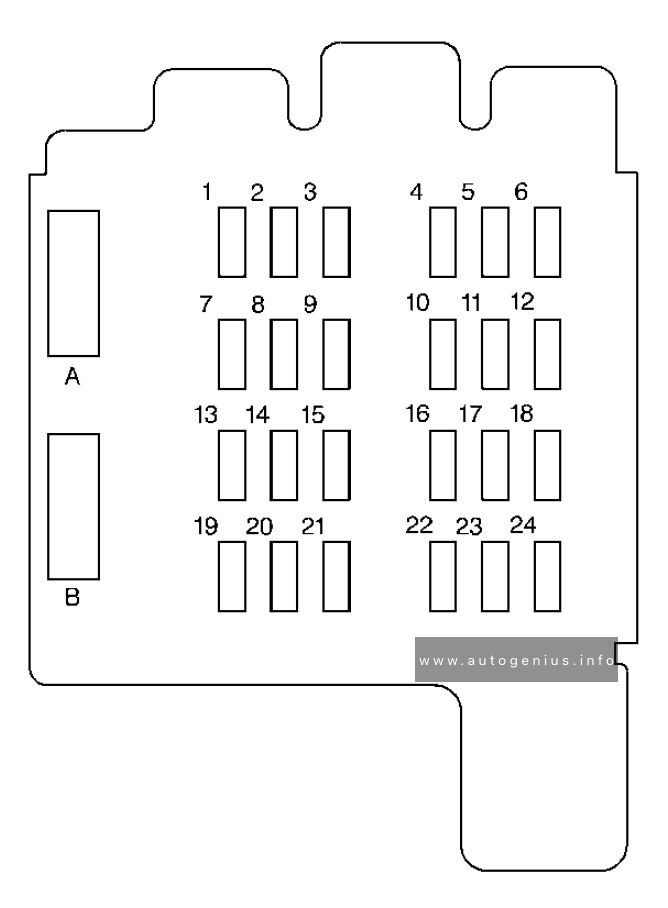
Assignment of the fuses in the passenger compartment
| Fuse/Circuit Breaker | Usage |
| 1 | Stop/Turn/Hazard Lamps, CHMSL, ABS |
| 2 | Radio ACCY, RR Seat Audio Controls |
| 3 | Courtesy Lamps, Glove Box Lamp, Dome Reading Lamps, Vanity Mirror Lamps, Courtesy Lamps |
| 4 | DRL Relay, Instrument Panel Cluste |
| 5 | Rear Defogger |
| 6 | Cruise Module, TBC Module, Instrument Panel Cluster, Cruise Control Switch, Electrochromic Mirror |
| 7 | Power Outlets, DLC, Subwoofer Amplifier |
| 8 | Crank Circuit Fuse, Park/Neutral Switch, Starter Enable Relay |
| 9 | License Plate Lamp, Taillamps, Parking Lamps, Ashtray Lamp, Panel Lights, Trailer Taillamps, Front and Rear Sidemarker Lamps, Door Switch Illumination, Headlamp Switch Illumination, Rear Seat Audio Illumination, TBC Module |
| 10 | Air Bag System |
| 11 | Not Used |
| 12 | L, M1, M2 Blower Motor, Rear A/C Relay Coil, Front Cont. Temp. Door Motor, HI Blower Relay, Defogger Timer Coil |
| 13 | Cigarette Lighter, Door Lock Switches, Dutch Door Release Module |
| 14 | Cluster Illum, HVAC Controls, Chime Module, Radio Illumination, Rear Heat Switch Illumination, Rear Wiper/Washer Switch Illumination, Rear Liftgate Switch Illumination, Remote Cassette Illumination, O/H Console, TBC Illumination |
| 15 | TBC Module, Headlamp Relay |
| 16 | Front Turn Signals, Rear Turn Signals, Trailer Turn Signals, Back-Up Lamps, BTSI Solenoid |
| 17 | Front Wipers, Front Washer Pump |
| 18 | VCM-Ign 3, VCM-Brake, Cruise Stepper Motor Signal, ATC Module |
| 19 | Instrument Panel Radio: ATC (Main Feed), 2000 Series (Standby) |
| 20 | PRNDL/ Odometer, TCC Enable and PWM Solenoid, Shift A and Shift B Solenoids, 3-2 Downshift Solenoid, Instrument Panel Cluster, VCM Module |
| 21 | Pwr Adj Mirrors |
| 22 | Not Used |
| 23 | Rear Wiper, Rear Washer Pump |
| 24 | Not Used |
| A | (Circuit Breaker) Power Door Lock Relay, 6-Way Power Seats |
| B | (Circuit Breaker) Power Windows |
Engine Compartment Fuse Box
Fuse box location
The underhood fuse block is located toward the rear of the engine compartment on the driver’s side of the vehicle.
Fuse box diagram
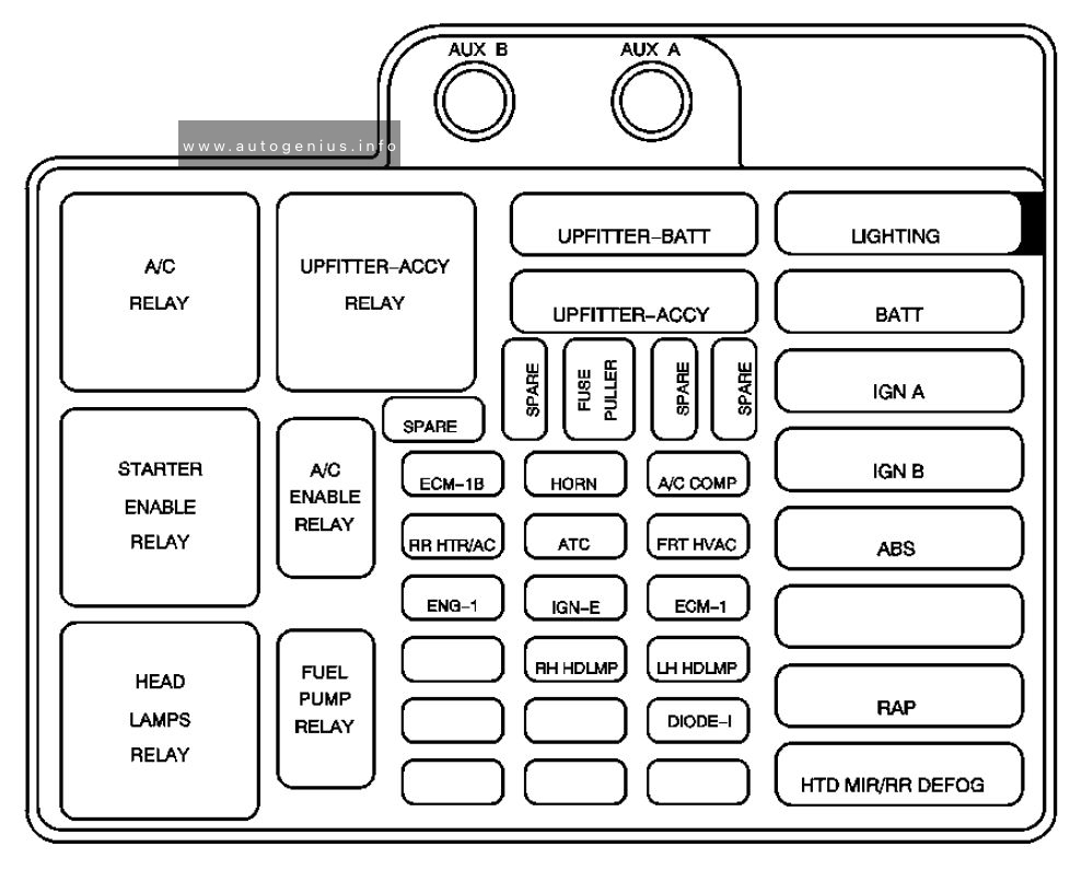
Assignment of the fuses in the engine compartment
| Feed | Usage |
| AUX B | Upfitter Battery Feed |
| AUX A | Upfitter Accessory Feed |
| Relay |
| A/C Relay (Rear Heat and A/C) |
| Upfitter-ACCY Relay |
| Starter Enable Relay |
| A/C Enable Relay |
| Headlamps Relay |
| Fuel Pump Relay |
| Fuse/Circuit Breaker | Usage |
| UPFITTER-BATT | Upfitter Battery Power Stud, Trailer Wiring Harness |
| UPFITTER-ACCY | Upfitter Accessory Relay |
| Spare | Not used |
| Fuse Puller* | — |
| Spare | Not used |
| Spare | Not used |
| ECM-B | Fuel Pump Relay and Motor, VCM, Oil Pressure Switch/Sender |
| HORN | Horn Relay and Horn |
| A/C COMP | A/C Enable Relay and Compressor |
| ATC | Active Transfer Case-L Van |
| FRT HVAC | Front Heater and A/C |
| ENG-I | Oxygen Sensors, Camshaft Position Sensor, Mass Air Flow Sensor, Evaporative Emission Canister Vent Solenoid |
| IGN-E | A/C Enable Relay Coil |
| ECM-I | Fuel Injectors 1-6, Crankshaft Position Sensor, VCM, Coil Driver Module (EST), Ignition Coil |
| RH HDLMP | Right Headlamp |
| LH Headlamp | Left Headlamp |
| DIODE-A/C Coil | A/C |
| LIGHTING | Courtesy Fuse, Pwr. Adj. Mirrors Fuse, TBC-Battery Fuse |
| BATT | Power ACCY CB, Stop/Hazard Fuse, Auxiliary Power Fuse, Cigarette Lighter Fuse, Radio Battery Fuse |
| IGN A | Starter Relay, Ignition Switch |
| IGN B | Ignition Switch |
| ABS | Electronic Brake Control Module |
| RAP | Radio Accy, Power Windows |
| HTD MIR/RR DEFOG | Rear Window Defogger, HVAC Control Head |
| A fuse puller is included in the underhood electrical center | |
WARNING: Terminal and harness assignments for individual connectors will vary depending on vehicle equipment level, model, and market.