MG HS (2019 – 2023) – fuse and relay box diagram
Years of production: 2019, 2020, 2021, 2022, 2023
The MG HS, a compact crossover, has been in production since 2019. This article features fuse box diagrams for the 2019, 2020, 2021, 2022, and 2023 models, provides details on the locations of the fuse panels inside the vehicle, and explains the function of each fuse (fuse layout).
Passenger Compartment Fuse Box
Fuse Box Diagram
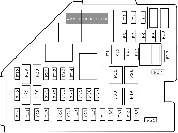
Assignment of the fuses in the passenger compartment
| No. | A | Protected components |
| F1 | 10A | Supplemental Restraint System Sensing and Diagnostic Module, DC-DC Converter, Communication Module, Shifter Control Unit, Instrument Pack, Body Control Module, SDM Auxiliary Display Module |
| F2 | 7.5A | Transmission Control Module, Reverse Lamp Switch, Engine Control Module |
| F3 | 5A | Front View Camera Module, Forward Detection Radar |
| F6 | – | – |
| F7 | – | – |
| F8 | 15A | Front Console Power Socket |
| F9 | 5A | USB Charging Port |
| F10 | – | – |
| F11 | 7.5A | Heated Exterior Rearview Mirror |
| F12 | 25A | Heated Rear Window |
| F13 | – | – |
| F14 | – | – |
| F17 | – | – |
| F18 | 30A | Rear Left Window Regulator |
| F19 | 5A | EPB Switch, Gear Display |
| F20 | 30A | Rear Right Window Regulator |
| F21 | 10A | Front Right Seat Heater Relay |
| F22 | 5A | Data Link Connector |
| F23 | 10A | Heated Front Left Seat |
| F24 | 10A | Gateway |
| F25 | 30A | KLR Relay |
| F26 | 30A | Passenger Window Regulator |
| F27 | – | – |
| F28 | 5A | PEPS Control Unit, Spare Coil |
| F29 | 10A | Gateway |
| F30 | 5A | Driver Window Combination Switch, Rain/Light Sensor |
| F31 | – | – |
| F32 | 5A | Atmosphere Lamp Control Module |
| F33 | 5A | Supplemental Restraint System Sensing and Diagnostic Module |
| F34 | 5A | Communication Module |
| F35 | 10A | Digital Audio Broadcasting (DAB) Module |
| F36 | 10A | Electronic Steering Column Lock Control Module |
| F37 | 20A | Driver Power Seat Adjustment |
| F38 | 30A | Driver Window Regulator |
| F39 | 30A | Blower |
| F40 | 15A | Entertainment System |
| F41 | 5A | Upper Centre Console Switch |
| F42 | 10A | HVAC Control Module |
| F43 | 5A | Instrument Pack |
| F44 | 5A | Rear Driving Assist System |
| F45 | 30A | Sunroof Motor |
| F46 | 5A | Tyre Pressure Monitoring System |
| F47 | 30A | Sunshade Motor |
| F48 | 20A | Front Passenger Power Seat Adjustment |
| F49 | 30A | Power Liftgate Control Module |
| F50 | – | – |
| F51 | 30A | Rear Window/Exterior Rearview Mirror Heater Relay |
| F52 | 10A | KL15 Switch Relay |
| F53 | 20A | Shifter Control Unit |
| F54 | – | – |
Engine Compartment Fuse Box
Fuse Box Diagram
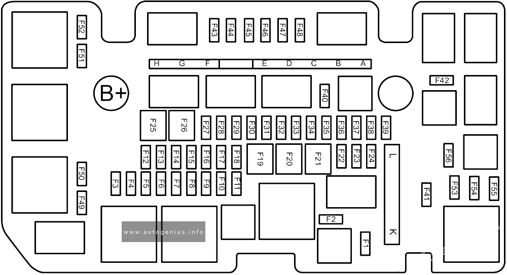
Assignment of the fuses in the engine compartment
| No. | A | Protected components |
| F1 | – | – |
| F2 | – | – |
| F3 | 10A | Front Fog Lamp |
| F4 | 25A | Body Control Module |
| F5 | 25A | Body Control Module |
| F6 | – | – |
| F7 | 10A | Engine Control Module |
| F8 | – | – |
| F9 | 15A | Horn |
| F10 | 5A | Transmission Gear Shift Actuator |
| F11 | – | – |
| F12 | 25A | Body Control Module |
| F13 | 25A | Body Control Module |
| F14 | – | – |
| F15 | – | – |
| F16 | – | – |
| F17 | – | – |
| F18 | – | – |
| F19 | – | – |
| F20 | 30A | DC-DC Converter |
| F21 | 30A | DC-DC Converter |
| F22 | – | – |
| F23 | – | – |
| F24 | 15A | Rear Wiper Relay |
| F25 | 30A | DC-DC Converter |
| F26 | 25A | Body Control Module |
| F27 | 10A | Windscreen/Rear Window Washer Relay |
| F28 | 25A | Super Lock Relay |
| F29 | 25A | Body Control Module |
| F30 | 25A | Front Wiper Relay |
| F31 | – | – |
| F32 | – | – |
| F33 | – | – |
| F34 | – | – |
| F35 | – | – |
| F36 | 10A | A/C Compressor Relay |
| F37 | – | – |
| F38 | 15A | Fuel Pump Relay |
| F39 | 5A | Crank Signal |
| F40 | – | – |
| F41 | – | – |
| F42 | – | – |
| F43 | 5A | DC-DC Converter Relay, Fuel Pump Relay, A/C Compressor Relay, Clutch Position Sensor, Brake Pedal Switch, Neutral Position Sensor, Cooling Fan Relay Box |
| F44 | 15A | Electronic Thermostat, WT Valve – Intake, WT Valve – Exhaust, Upstream Oxygen Sensor, Downstream Oxygen Sensor, Canister Shut off Valve |
| F45 | 10A | Engine Oil Control Valve, Canister Control Valve, Exhaust Gas Control Valve, Relief Valve |
| F46 | 15A | Engine Control Module |
| F47 | 15A | Ignition Coil, Air Flow Sensor |
| F48 | – | – |
| F49 | 10A | Right Headlamp |
| F50 | 10A | Left Headlamp |
| F51 | – | – |
| F52 | – | – |
| F53 | – | – |
| F54 | – | – |
| F55 | – | – |
| F56 | – | – |
| MF1 A | 80A | Electric Power Steering Control Module |
| MF1 B | 40A | 7-speed Dual Clutch Transmission Control Module Relay |
| MF1 C | 40A | Dynamic Stability Control System (pump) |
| MF1 D | 40A | Dynamic Stability Control System (valve) |
| MF1 E | – | – |
| MF1 F | 30A | Starter Relay |
| MF1 G | – | – |
| MF1 H | 50A | Cooling Fan |
| MF2 K | 100A | Passenger Compartment Fuse Box |
| MF2 L | 30A | Electric Vacuum Pump |
| SB8 | 40 | Blower relay |
WARNING: Terminal and harness assignments for individual connectors will vary depending on vehicle equipment level, model, and market.